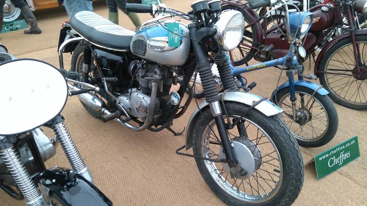
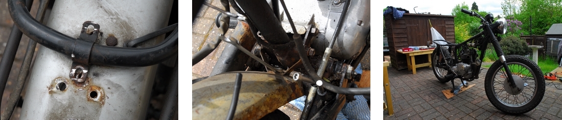
I'd just past my 70th birthday but I felt I had another build or two left in me. So what to rebuild this time? Didn't really want to do another Bonneville but I do have a fair bit of experience with older Triumphs and quite a few special tools so it seemed sensible to look for another of Meriden's finest. I started looking for a 500cc model... a Tiger 100 or perhaps an older 5TA 'Speed Twin' but I couldn't find anything suitable. They had either already been restored and were ridiculously expensive or heaps of junk that were still ridiculously expensive. Then I had a bit of luck; Cheffin's were having one of their vintage machinery auctions at their Cambridgeshire sales ground and had emailed me a link to their on-line catalogue. There were a number of old bikes being auctioned but one machine in particular caught my eye. It was Lot 1540, a 1968 350cc Triumph T90, better known as the "Tiger 90"... That would do very nicely.
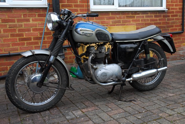
 The auction was on Saturday, April 16th 2016 but there was the opportunity to view the items for sale on the Friday afternoon. I'd recently sold the Moto Guzzi Le Mans so I had a significant amount of wedge available. The plan was to go up to Ely on the Friday afternoon and look at the bike. If it was OK and I wanted to bid for it, I'd stay in Ely overnight and attend the auction on Saturday. And that's exactly what happened. The bike was very much OK... a bit tatty but it was original and totally unmolested. It had only had 3 owners, the last two being members of the same family who had owned it between them for the last 40 years or so. It had 22,000 genuine miles on the clock, backed up by all the old MOT certificates and receipts that came with it and most importantly, the engine and frame numbers matched... It was still the way it had left the factory. Did I want it...? Yes, indeed I did! A visit to the site office was required to register my intention to bid. A few formalities completed, a £20 'registration fee' was handed over and I came away with a card upon which was printed my "Bidder's Number" - V6391K. All I had to do was hold up that card if I wanted to bid and make sure the auctioneer saw it. Easy, peasy.
As planned, I stayed in Ely overnight and drove back to the sale ground on Saturday morning. The bike auction was scheduled to start at 1:00 p.m. and there were a number of 'lots' before the T90 came up. To make sure I didn't miss it (and to get an idea of the protocol as I'd never bid at an auction before) I got to the marquee early and took a seat in the centre of the room, a few rows back... right in front of the auctioneer. Bidding was brisk and the bikes sold quickly... soon it was the little T90's turn. The auctioneer opened the bidding at £3,000 but nobody bid so the price quickly tumbled to £1,500. I stuck my card in the air, the auctioneer saw it and we were away... There were two other bidders in the room and one on-line. The price quickly rose to £3,500 and the room bidders had dropped out. Just me and the on-line bidder left. I'd mentally set my bidding limit to £4,000 but the online bidder called it quits when I raised the bidding to £3,800. It was all over very quickly but the adrenaline rush when the hammer came down and the auctioneer pointed at me and said "V6391K - Yours, sir. Well done." took a little while longer to abate. The little T90 was mine for £3,800 plus the "bidder's premium" of 8% + VAT. That came to a grand total of £4,164.80
Another trip to the site office and this time a rather larger chunk of wedge changed hands. I came away with the V5C/2 'green slip', a thick folder full of 'stuff' relating to the bike and, I guess, a glazed look in my eyes... I needed a beer but the best I could do here was coffee. Reality check time... I was the new owner of the Tiger 90 but having bought it, I had to get it home. I'd driven up in the car and whilst it's fairly big, it ain't THAT big so I needed an alternative plan. Fortunately, with unusual, for me, foresight, I'd already got a quote for delivery from a local haulier on the off-chance that I might need his services. Time to phone him again, this time to arrange a collection from the auction ground and delivery to my home. That done, it was time to head home myself... with a brief stop on the way for that aforementioned beer! The bike turned up on the back of a trailer the following Friday morning.
So what to do with it...? Do I keep it absolutely 'standard' or bring it up-to-date as I did with the Bonneville? Probably somewhere between the two but first off, some petrol in the tank, check the oil level and fire it up. It started and ran nicely so it went into the garage with the Bonneville until I could get it MOT tested and taxed. The Two Wheel Centre in Harpenden obliged with the former and that done, the local Post Office sorted out the road tax for me. As it was classed a 'Historic Vehicle' there was no fee to pay but you still have to go through the formalities. Since then I've ridden it a couple of time and put about 150 miles on the clock. It performs well and apart from a little clutch slip before it's properly warmed up, there are no problems. All in all, I'm well satisfied with the bike. It's totally honest and will make a great restoration project. I'll keep this page updated with my progress, so watch this space.
Thursday, 19th May, 2016
 Time to start the dismantling process. The bike has been brought up the back of the house. When I was married, it was a patio; now it's the area where bikes get dismantled and in due course, put back together again. I'll start with the easy stuff. The four screws holding the seat hinges to the set pan came out... They're 1/4" UNF, 1/2" long hex head screws with a spring washer. The seat pan look sound with a little surface rust. Stripped, blasted and powder coated it'll be good for another 50 years. I'll probably send it up to Leighton's to be sorted with new foam padding and a new cover as this one has a split in the rear end. The tank came off easily with just three bolts holding it on. One central bolt at the rear and one each side underneath at the front. The front bolts are drilled for locking wire but there was none in them. The bolts and cup washers were rusty, the rubbers soft and a bit perished so the whole lot will be replaced when the time comes. The tank is in great shape... no dents and the inside is rust free so nothing to do there other than a new paint job. Colin in Chelmsford did a good job on the T120R tank but this time I'll let Ernie over near Baldock do the respray if he has time. I've seen some of his spray jobs on a couple of local 'choppers' and it was very good indeed.
Having got the tank and seat off, it was time to have a go at the exhaust system. The left pipe was loose at the head anyway and that came off without any problem. The right pipe was a little more problematic. It was fixed very firmly at the head. The finned clamp bolt was rusty and 'rounded off' so that wasn't going to come undone without a fight. It got one... with my angle grinder and lost. Having got rid of the clamp, the pipe still refused to budge so it was cut off just short of the cylinder head stub. The remaining portion was split with a cutting disc in the Dremel and that was that... Problem solved. I noticed that both silencers had been damaged underneath by the centre stand... That will need looking at down the line. There's obviously something not quite right in that department.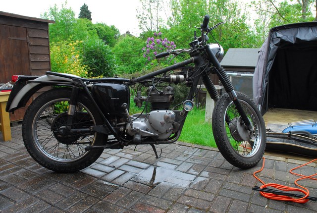 The front mudguard and stays were next. I expected a little trouble here and got it. The four screws securing the front and bridge stays to the mudguard blade were rusted solid and all four sheared off when I applied some pressure. Not a real problem as I'll replace them with stainless screws in due course. The stays themselves are pretty pitted and rusty but I'll clean them up and smooth them off before they go for powder coating. The mudguard its self is in fine condition apart from the badly faded paintwork. It's not dented or twisted out of shape in any way and there is only minimal surface rust at the bottom. The only other thing I did today was drain the oil tank.
Friday, 20th May, 2016
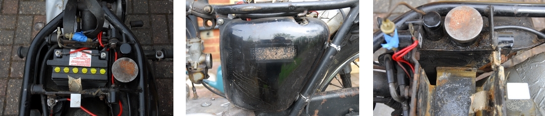
I spent a couple of hours this morning taking off a few more parts. The battery was disconnected and removed. It's not the right one and fits the battery carrier like a pound of sausages up the Blackwall Tunnel. The battery strap, what there was left of it, was well perished and will need to be replaced along with the buckle and spigot nut that goes with it. More parts on the 'To Get' list. The side panel / tool box was next. That has the wrong screw holding it in place. It should be a screw with a proper 'knob' on it... one more for the list. The rubber bushes that locate the panel are also soft and 'squidgy' so I'll replace those too. They are the same part as the battery carrier bushes and I think I have some of those left over from the Bonneville rebuild. Having sorted out that side, it seemed sensible to remove the battery carrier and oil tank. That would have been much more easily accomplished, had I realised that the battery carrier tray could be separated from it's mounting rails and removed first. Trying to get the whole lot out in one go was problematic as the oil tank was in the way and conversely, I couldn't get the oil tank out because the battery carrier was in the way... I did manage to get it all out in the end and then, as one does, realised that there was an easier way... Ho hum.
The last things I took off this morning were the rear mudguard and the brackets and stray that support it. As expected, the 50 year old screws and nuts didn't give up without a fight. There was no way they were going to undo so after brief fight with my angle grinder, the mudguard was free and stripped. The support rail, bridge piece and the number plate were all removed. These will be cleaned up and powder coated in due course. The wiring protector that was attached underneath the mudguard will be replaced as that has rusted away too far to be realistically salvaged. All in all, a satisfying mornings work.
Monday, 23rd May, 2016
The weather has decided to be kind to me. Today the sun was shining and there was a gentle breeze; just right for working on the T90. I started this morning by cleaning up the petrol tank and removing the badges and the stuck on rubber knee grips. 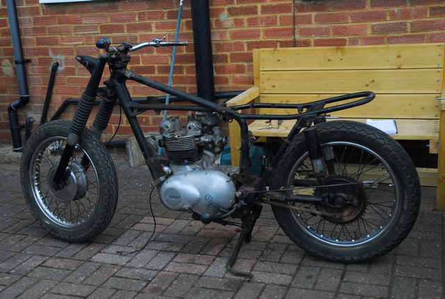 They are actually in surprisingly good nick and they'll go back onto the tank eventually, after it's been painted. The dried on mud and road filth that coated the underside of the mudguards was blasted off with a pressure washer. Hopefully, I'll get the tinware up to the painter (Ernie or Colin, not sure who will get the job yet) in the next few days. That will give them plenty of time to complete the respray before I need them back again. Having done that, I stripped off the old wiring harness. It had definitely seen better days and I'll create a new one in due course. The instruments, headlamp, ignition coils, capacitor pack, horn and zener diode all came off. The headlamp shell, I discovered, had been changed at some time in the past. The one currently fitted was in good condition but unfortunately it's not the correct one for the bike. This one was intended for one of the later Triumph 'triples' and had been cobbled together with some very non-standard spacers to make it fit. That won't be going back on.... The clutch cable and lever were next to come off. The cable outer sheath was damaged in a number of places and that was consigned to the rubbish bin. The carburettor cable and air slide cable were next. They too will be replaced with new ones when the time comes. The two cylinder head steadies and the rocker shaft oil feed pipe were removed in preparation the engine removal. The last thing to come off today was the chain guard. The nut and bolt holding it at the front weren't going to shift so it was another job for the angle grinder and cutting disc. My "Parts to Get" list is growing longer by the day.
Tuesday, 24th May, 2016
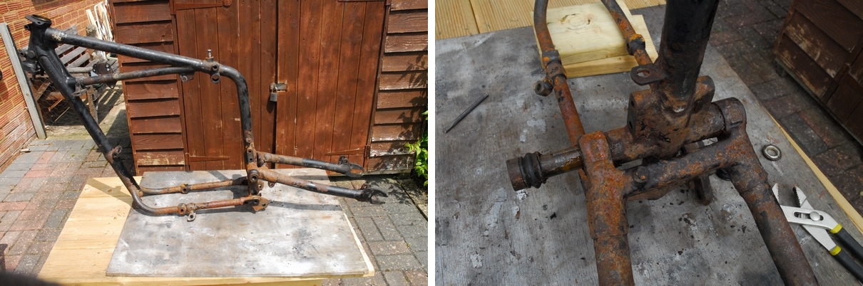
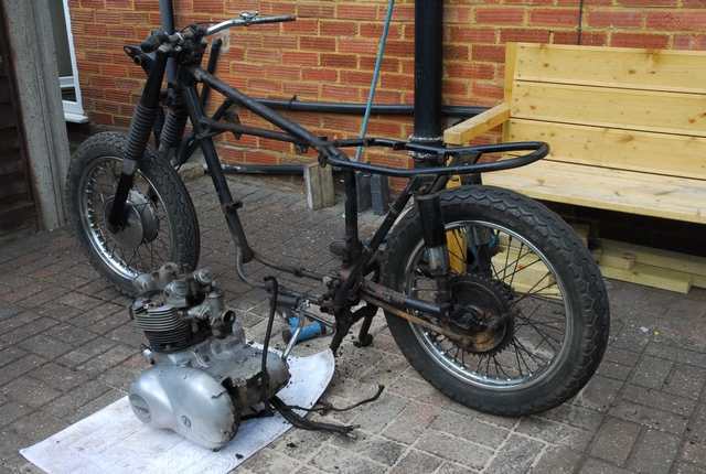 The objective today was to get the engine out of the frame but there were a few bits and pieces to take off before that could be accomplished. The rear brake pedal and operating rod were first on the list. That was just a matter of undoing the pedal pivot nut and the adjusting nut on the end of the brake rod. No problem there. The foot rests, however proved a little more difficult. They are fitted on a tapered spigot and probably have never been moved since the bloke at the Meriden factory bolted them on. Breaking those tapered joints called for a little finesse with a 4lb lump hammer. The rear engine plates were already loose as the studs held the rear mudguard fixing that I'd removed earlier so they were quickly removed. That just left the front engine plates and the long stud under the engine. It was just a case of undoing a few nuts which fortunately gave up without too much of a struggle. I placed a mat down beside the bike and lifted the engine clear of the frame and lowered it onto the mat. All very easy, really. It was quite heavy but just about manageable on my own. Having got the engine out, I could see all the crud that had built up under the engine and around the lower frame members. That was easily sorted. The rolling chassis was moved out onto my alternative work area (the back access road) where the cleaning could take place. The frame was liberally soaked in 'Gunk' and that worked into all the crud with a stiff brush. I find it's better to let it soak for a while so while that was soaking, I soaked up a bottle of cold beer that I had left over from Christmas!! A pleasant half hour went by while I lounged in the sun and drank my beer. With that all gone, the frame got another brushing and the whole lot hit with a pressure washer. It made a mess of the access road but the frame was a lot cleaner! The same method (without the beer, this time) was used to clean the mess off the outside of the engine, having first covered the inlet and exhaust ports with disposable nitrile gloves. The engine was then moved into the workshop (my shed, really) and set up in its frame on the bench. That was all for today...
Wednesday, 25th May, 2016
After a leisurely pub lunch at the Strathmore Arms, Les drove me over to see Ernie at Clothallbury Farm, near Baldock. Ernie has agreed to paint the tank and mudguards for me so we left them with him. Had a look at some of his current work and it really is superb. If my paintwork comes up like that I'll be well pleased.
Thursday, 26th May, 2016
Spent a couple of hours this morning cleaning up all the brackets, plates and other assorted ironmongery that I want to get powder coated gloss black. There's still quite a few parts to take off the frame but at least I can get the work started. I'll take the box full of bits up to CWC in Coleshill tomorrow.
Thursday, 2nd June, 2016
A successful trip up to CWC... They will bead blast and powder coat all the bits I took up and they should be ready sometime next week. They will have to wait, though as next week I'll be in Ireland with my brother. I'll collect them when I get back.
Ernie phoned me a couple of days ago and requested the frame and engine numbers so that his paint supplier could supply the correct colour (Riviera Blue and Silver). Yesterday Les and I went over to see him, pay some 'up-front' money and drop off the oil tank and side panel / tool box which he's going to paint gloss black and put the relevant transfers on. The weather has been a touch inclement of late and I've not progressed much. Hopefully that will change when I get back from holiday.
Sunday, 12th June, 2016
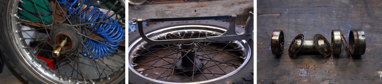
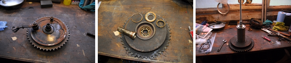
Back from a week in southern Ireland with my brother and raring to get on with the little T90. While I was away, CWC phoned to say that the box of bits I took up a couple of weeks ago are ready for me to collect. It makes sense and will save a journey if I take the wheels up to be refurbished at the same time so today I took both wheels out of the frame. I need to take the old tyres off as they are 10 years old and well past their "sell by" date. Fortunately, I can get mate Les at the Two Wheel Centre to whip 'em off on his pneumatic machine. I still needed to remove the bearings, though as any trapped grease will melt and run out during the powder coating process and ruin the finish. I started with the rear wheel. It's a QD (quickly detachable) item so it was just a case of undoing the axle and withdrawing it, making sure I make a note of how the spacers and adjusters are fitted. Then is was a simple job to pull the wheel away from the brake drum and drop it out of the swinging arm. There is a rubber sealing ring around the splines on the hub that will need replacing as the one fitted has gone soft and compressed.
That done, the next job was to undo the nut on the end of the bearing tube and lift off the speedometer drive gearbox. Sounds simple but judging by the amount of dried grease and dirt covering them, they hadn't been removed in a very long time, if ever, so I was expecting a fight. I cleaned all the crud away from the nut and it actually undid quite easily. It was a bit of a struggle separating the speedometer drive gearbox from the wheel but it came off eventually with a little persuasion. With that out of the way, I could lift the spacer tube off and gently tap the bearing tube through the the bearings and remove that and the bearing cover plate. So far, so good. The drive tube for the speedometer was next to tackle. That's screwed into the hub and has a LEFT HAND THREAD. I found that my hacksaw frame was exactly the right size to undo it. With that removed and also the bearing shield lifted out, it was time to persuade the bearings to part company with the hub. There is a spacer tube between the bearings that make life a bit difficult but with a little ingenuity, some threaded rod, a short length of tube and a slide hammer, the bearings were removed undamaged but as they are relatively inexpensive, I'll replace them anyway. All the spacers and grease retainers were removed in good condition so they can go back although as I'll replace the bearings with new ones that have integral shields, they won't strictly be necessary. One wheel down... one to go.
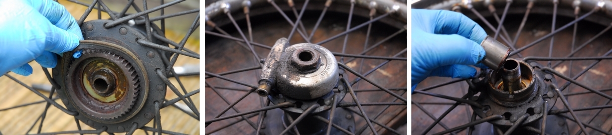
The front wheel was somewhat less complicated. After removing it from the forks I needed to take the front brake plate off. That was held by the large nut on the axle. With hind-sight, I should have slackened it off while the axle was still clamped in the forks but I managed with a piece of rag wrapped round the axle and a pair of 'Mole' grips to hold the axle still while I attacked the nut with an open ended spanner. That sufficed although there are a couple of marks on the axle from the 'Mole' grip that I'll have to dress out with a Swiss file before it goes back. Once the nut was off it only took a little gentle persuasion to separate the brake plate from the hub. The shoes and drum are in remarkably good condition with not a trace of scoring. That's a result! The chrome plated cover plate on the opposite side was simply tapped off with a soft drift. It's only a light press fit onto the hub.
The bearing retaining ring inside the brake drum is also LEFT HAND THREAD and requires a peg spanner to undo it. Fortunately, I have such a tool and so the ring was not a problem. With that out of the way, the bearing on that side can be driven out by giving the opposite end of the axle a sharp clout with a piece of hardwood (to protect the end) and a club hammer. After removing the circlip and grease shield on the other side, that bearing is removed in a similar manner to the first.
The wheels were degreased with white spirit and they're ready to have the tyres removed, hopefully tomorrow and I can then take them up to Coleshill.
Monday, 13th June, 2016
I took the wheels over to the Two Wheel Centre this morning and Nick obliged with the tyre removal as Les was busy rebuilding a Hayabusa engine that some careless person had destroyed the gearbox on. Ho hum... Tyres removed, I loaded the wheels into the motor and drove up to CWC in Coleshill. Both wheels will be dismantled and the hubs degreased. The rear wheel QD hub will be bead blasted to remove the old black paint and rust then given a gloss black powder coating. The cast iron front hub will be blasted to get rid of the old silver paint and powder coated 'Hybrid Silver'. After that, both will be built up with 18" WM2 stainless steel rims using stainless steel spokes. No more rusty wheels for me. It might not be original but it's a hell of a lot easier to keep clean. Both wheels will have new a rim tape, a new Michelin inner tube and be fitted with new Dunlop K82 tyres; a 3.25 x 18" on the front and a 3.50 x 18" on the rear.
The assortment of parts I took up previously had been powder coated gloss black and were waiting for me when I arrived. I took 29 parts up and got the same 29 parts back... that's a result! Given the rusty and corroded state some of the 60 year old parts were in, they've done a remarkably good job with the painting. While some of the worst parts don't look exactly brand new, they are at least black and shiny and you can't see the imperfections unless you look really closely. I'm well satisfied as it's not my intention to build a "100 point trailer queen". When it's finished it will be a 'rider' and I hope I'll be proud to ride it.
Tuesday, 14th June, 2016
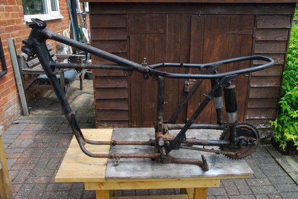
Having sorted the wheels out, today I set about removing the front fork assembly. Not a difficult job, really. The steering damper came off first but the workshop manual never mentioned anything about a grub-screw in the rear of the bottom yoke that secured the damper nut. That confused me for a bit so the damper 'clutch' remained on the bottom yoke for the time being. The nuts on the handlebars eye bolt mountings were undone and the handlebar assembly taken away. That gave me clear access to the fork stanchion cap nuts. They were no problem because I had a 1.1/2" A/F socket that I acquired for the Bonneville forks. Pause for thought here... The steering head bearings are the old type cup and balls so as soon as I release the forks, forty 1/4" diameter steel balls are going to drop out all over the floor. Simple answer was to put a strap around the bottom yoke and the frame to stop the fork assembly from dropping out when the top yoke is released.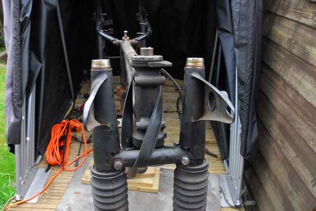 Having secured the forks, I undid the sleeve nut on the stem and gave the top yoke a tap from underneath to release it from the fork stanchions so that it could be lifted off. The top bearing cup and dust shield was lifted off to reveal the 20 steel balls. They were carefully removed and put on a small zip-lock bag. That done, the strap was slowly released and the fork assembly lowered from the frame. The balls stayed where they should, held by the grease in the lower bearing cup. All good so far. I collected the balls and then knocked out the bearing cups from the frame and took the lower bearing cup off the bottom yoke. The bearing tracks on the top bearing are showing signs of 'chatter' so both bearings will be replaced, probably with the later taper roller bearings. The forks were up-ended in a drain tray to let the oil drain out.
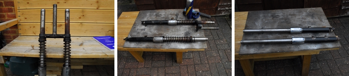
The top shrouds that carry the headlamp were lifted off to reveal the somewhat rusty stanchions. The old rubber gaiters were cut off after removing the securing clips. There's some rust but it's probably not as bad as it looks. The lower half that runs in the oil seal doesn't actually look that bad. I'll see better when the legs are out of the bottom yoke and the springs removed. That was the next job. The rust was cleaned away as best I could, the cap nut was replaced to protect the top thread and the legs gently tapped down to release them from the bottom yoke. That done, the springs, abutments and cork washers were taken off. They will be cleaned, the abutments powder coated and the cork washers replaced. The stanchions were degreased and the rust removed with a very fine silicon carbide rubbing block. Actually, they've cleaned up very well. There is some pitting where the rust was heaviest but it was all above the oil seal limit so it really doesn't matter enough to warrant replacing them. That is good news. I will replace the 'Oilite' bushes and oil seals as they are cheap enough.
All the component parts were degreased and cleaned. The top yoke needed some work as the bonded rubber bushes for the handlebars will have to come out as they won't survive the high temperature in the powder coating oven. I thought they would put up a fight and they did... Without a hydraulic press, they had to be removed the old way with a hacksaw. The steering lock also needed to come out as it was broken and will be replaced. That was just a case of drilling out the blanking plug that covers the securing screw and then taking out the screw. The lock barrel could then be knocked out with a suitable soft drift. All in all, things are progressing nicely.
17th June, 2016
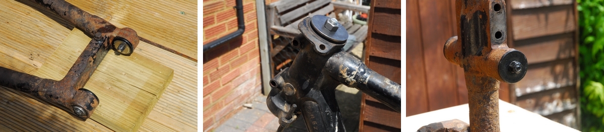
 Apart from the rear brake drum assembly and the front fork legs, the bike has now been broken down into its component parts. I'll take the fork legs apart when the hook wrench I've ordered arrives. The rear brake drum assembly will be dismantled, cleaned and inspected in due course. The brake plate and operating arm will be powder coated. The ball bearing will be replaced if it shows any sign of wear. So... what have I done today? Well, first off I removed the centre stand. That was just a case of knocking back the tab washers on the nut and undoing same. The pivot bolts were then unscrewed. They're worn and new ones will be used when I put it all back together. The rear suspension units were next. The top bolts were already loose as they secured the rear mudguard support loop and that came off a while back. The bottom bolts were reluctant to move but a suitable size socket and a long breaker bar soon had had them undone. The suspension units are well past their sell-by date so that's another item for my "to get" list. Having removed the rear suspension, removing the rear sub-frame was just a case of undoing and removing the swinging arm pivot bolts, two more nuts and bolts at the bottom and removing the nuts and stud at the top.
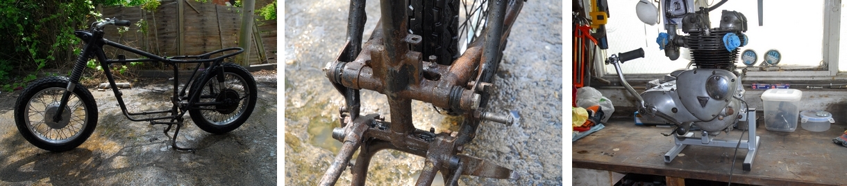
Removing the rear brake drum assembly was just a case of undoing the small nut that holds the torque arm to the brake plate and undoing the big nut that secures the axle assembly to the swinging arm. No problem there... Undoing the hex head screw at the other end of the torque arm, however, was a different matter. It has a thin head, and was very rusty. I just knew this one was going to be a problem. A socket spanner on my impact driver was the first attempt. That didn't budge it and was more likely to damage the hexagon head if I continued. It was looking more and more likely that I'd have to cut the head off with the angle grinder, then drill the old bolt out and re-tap the thread in the swinging arm. Time for some heat... The propane torch was fired up and that screw got the full treatment. It was sizzling nicely when I used the socket spanner and breaker bar on it. I really didn't think it was going to move... but it did. It gave up and allowed me to unscrew it... Result!!
That just left the swinging arm. Having already removed the bolts, it was just a case of drifting the old bearing axle out. It was due for replacement anyway as there was an unacceptable amount of play in the bearings. As it happened, it came out easily. That was pretty much it for today.
Sunday, 19th June, 2016
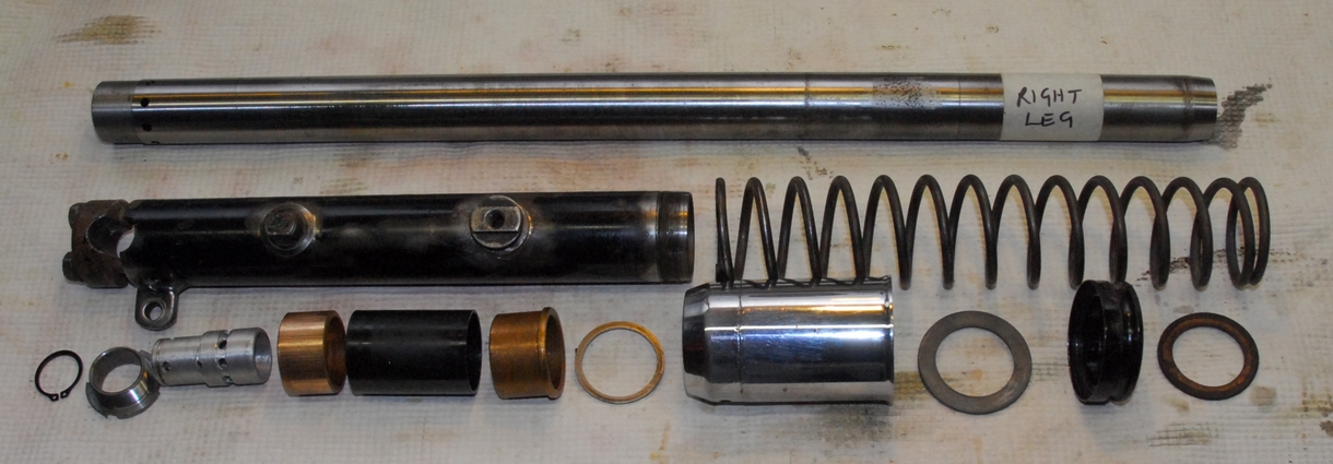
I had a couple of hours spare this morning so it was time to dismantle the front fork legs. That entailed unscrewing the chrome plated oil seal holder. This in turn, entails the use of a "C" spanner / "Hook" spanner / "Peg" spanner... call it what you will. The only one I had was the wrong size so I ordered the correct one a few days ago and it arrived yesterday. All I needed now was a vice large enough to hold the fork slider. That meant a trip over to my sister's house to use the one in my brother-in-law's garage. No big deal as they only live a few miles away. The new peg spanner did the job and the chromed sleeves were unscrewed from the fork sliders. A few sharp tugs on the stanchion and the whole lot came out. The two sintered bronze bushes will be replaced as they were noticeably loose on the stanchion. The chrome plated sleeves will be replaced as well as the plating has suffered and is rusty. New oil seal and o-ring will be fitted as a matter of course.
Friday, 24th June, 2016
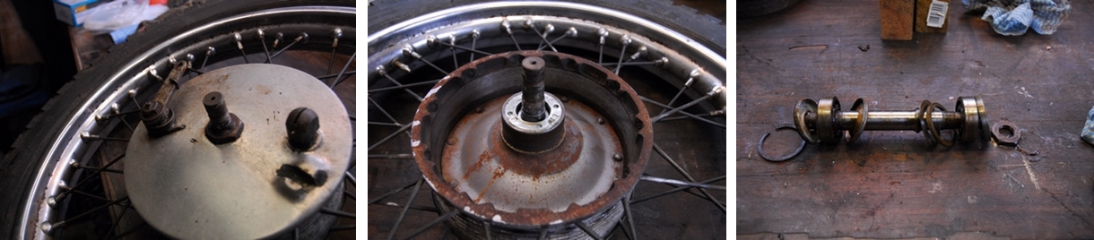
Only one more thing left to do and the dismantling is complete. That's the rear brake assembly. As the bike is fitted with a QD rear wheel, the brake plate, brake drum and final drive sprocket are left attached to the frame when the rear wheel is removed. The one large nut securing it had already been undone and the whole assembly removed. It was now just a case of taking it apart. The brake anchor plate, complete with shoes lifted off and was put to one side for the moment. The bearing spindle was tapped through the brake drum. The large circlip securing the bearing was removed along with the grease retainer / dust shield and felt washer. The bearing was pulled free from the drum with a length of threaded rod, a few nuts and washers and a short length of steel tube... in other words, my home made bearing extractor! The bearing felt OK until I cleaned all the old grease out. Then I could feel a significant amount of play so that will be replaced along with the old felt washer. The brake plate was then taken apart... Simply a case of removing the brake shoes, which was easy enough and then undoing the nut holding the actuating arm onto the cam spindle. That out of the way, the arm was persuaded to part company with the spindle and the spindle tapped out of the brake plate. The plate and the actuating arm will be powder coated black. It looks so much better than rust!
Well, basically... that's it. The bike is now in it's component parts, although the engine is still in one piece. That will be tackled later. The swinging arm bushes have been replaced. The old bushes split with a hacksaw before tapping them out. The new bushes pressed into the swinging arm. As expected, the bushes had closed up a little once they'd been pressed in and needed a few tenths of a thou taken out with a reamer to get a perfect fit on the new spindle. Straightforward engineering and I can do that! The new bushes have been masked off with steel washers to protect them during the powder coating process. The steering head bearing recesses and the swinging arm attachment boss on the main frame have also been similarly protected. Just need to get the whole lot up to Coleshill for powder coating and I can start the re-assembly of the rolling chassis. Happy days!!
Friday, 1st July, 2016
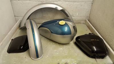
I made two 'phone calls on Tuesday. The first to Ernie to see how he was getting on with the paintwork. He told me it was all done, just needed to be 'mopped' so I could collect them on Wednesday. So on Wednesday, after a relaxed lunch at the Strathmore Arms, Les and I drove over to Clothallbury Farm to do just that. I was gobsmacked... The paintwork is superb. I was well pleased. Ernie, or Otto Racs, to call him by his correct name, had made a brilliant job of them. I only hope that the bike, when completed will do them justice.
The second phone call I made was to CWC up in Coleshill to see how they were progressing with the wheels. I seem to remember that the delivery was quoted at 10 to 14 days but the lass that I spoke to on the 'phone was in no doubt that for wheel building, the delivery was 4 to 5 weeks... A bit of a difference. The wheels wouldn't be ready for at least another fortnight. I had intended to take the frame up when I collected the wheels but that would put an unnecessary delay into the build so I made the extra journey up to Coleshill yesterday and took the frame and all the remaining parts to them. Hopefully, they should all be ready at about the same time so it will only be one more trip. As has become something of a tradition, I met up with friend Robert at the George & Dragon in Stoke Golding, the outlet for the Church End Brewery, for a swift pint and a sandwich before the drive back down the A5. Life is good.
Sunday, 3rd July, 2016
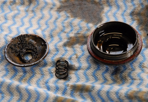
There was nothing to do on the rolling chassis until the bits come back from CWC so it was time to have a look at the engine. First job was to drain the oil from the crankcase, gearbox and primary chain case. About a cupful of oil came out of the crankcase, which was about what I expected. More worrying was the debris on the filter screen. More than I expected, gritty and altogether not very nice. None of it proved to be magnetic so it wasn't steel, which was good. Hopefully, I won't have to split the crankcases unless I find something serious further down the line.
The gearbox yielded about 350ml but there is almost certainly some oil trapped between the inner and outer covers so it's probably about right. The oil was a bit discoloured but it wasn't obviously contaminated with metal particles so that's promising as I don't really want to replace the gear cluster or any part of it unless I really have to.
I mentioned right at the start that there was a bit of clutch slip... well I think I know why! The clutch is in the primary drive case and that case should contain just 300ml of oil. I drained about a litre and a half of oil out. Now either the previous owner was a bit over enthusiastic or the crankshaft oil seal has blown, allowing engine oil from the crankcase to bleed through the main shaft ball bearing into the chain case. I suspect it's the latter. No big deal as I will replaced all the oil seals as a matter of course. 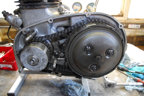 With the fluids drained, I decided to tackle the primary drive next. The cover was held in place with the original cross head screws not after market hexagon socket cap head screws and they were well rusty so I knew it was going to be a struggle. I tentatively tried a big Phillips screwdriver but that really wasn't going to do the job. All I'd succeed in doing would be to destroy the heads and I'd have to drill the screws out. Not a scenario that I wanted to contemplate. Time to bring out 'The Equaliser'... my impact screwdriver (if you don't know what that is... Google it!). After selecting the correct 'bit', the driver is offered up to the screw and whilst applying a bit of anti-clockwise torque with one hand you clout the end of the driver with a hammer. A cam in the screwdriver turns the bit whilst the hammer blow keeps the bit engaged in the screw head. All very simple and very effective. All 10 of the screws grudgingly gave up and came out without any damage. I suspect that they'd never been out since they were installed at the Meriden factory. A light tap with a plastic mallet to break the joint seal and the chain case cover came off. Hmmm... surprise, surprise... everything looks pristine in there. There's no heavy black sludge that would indicate the cush drive rubbers are breaking down. There is very little wear on the chain tensioner blade and not much wear in the chain either. The clutch spring adjusting nuts don't look like they've ever has a screwdriver on them, the alternator cable is still flexible and undamaged. This just confirms my suspicions that the cover has never been off. A very pleasing discovery that bodes well for the condition of the rest of the engine. The last job today was to remove the alternator stator. I'd already undone and removed the cable securing clip from the bottom of the crankcase so it was just a matter of undoing three nuts securing the stator, pulling it off the mounting studs whilst feeding the cable back through without damaging it. The alternator is the standard, single phase, 12v 10amp, two lead item.
Monday, 4th July, 2016
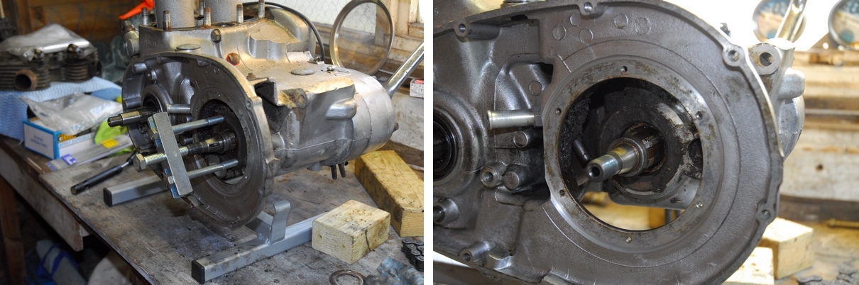
 I spent a couple of hours on the engine this morning. First job was to unscrew the alternator stator mounting studs. These were originally installed with a thread sealer and were pretty tight but they all came out without too much trouble. The threads will need to be cleaned and all the old sealer removed before re-installing them later. That done, the tab washer securing the crankshaft nut was tapped back and the nut undone. The alternator rotor was then pulled off the crankshaft. It was a slide fit and came off by hand. The woodruff key was also taken out and stored for safe keeping. Next was the clutch. The spring retaining screws were undone and the pressure plate removed, then the disc pack taken out of the clutch basket. I was expecting to find 5 friction plates as the workshop manual suggests but there were in fact 6. The clutch is actually identical to the standard Bonneville clutch. The plates show very little wear so I'll clean them up and re-use them. I couldn't remove the primary drive as the chain is endless and has no joining link which means that the clutch sprocket, chain and engine sprocket all have to be removed at the same time. Therein lay the problem. Whilst I had an extractor to remove the clutch, I didn't have one to pull the engine sprocket off the crankshaft splines. I was hoping that it would pull off easily... no such luck. That has now been rectified and the service tool is winging it's way to me as I type this. I've never objected to buying the correct tool for any job, if it makes my life easier.
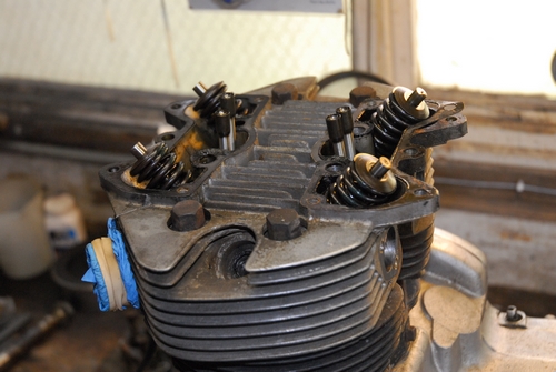
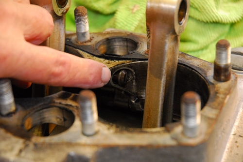 Time to start on the top end. The carburettor was removed from the manifold and the manifold removed from the cylinder head. The carb will need cleaning and checking out as the spark plugs were very black and sooty when I took them out. It may be that the engine was running rich so I'll need to check the jets. That done, the inspection caps in the rocker boxes were unscrewed so that I could see when both valves were closed and I could undo the screws and centre cylinder head studs. Both rocker boxes were taken off. That's when I spotted the first signs of any wear in the engine. There were significant 'dimples' in the ends of the valve stems where the rocker adjusting screws had been in contact with them. It maybe that the stems can be re-faced or I may have to replace the valves; it depends on what the valve heads are like when I take them out. The remaining head bolts were undone and the head lifted off. There was quite a bit of carbon build-up in the combustion chamber and on the piston crowns which also may indicate that the engine was running rich or perhaps burning a little oil. There was no obvious wear in the cylinder bores but I'll check them with an internal micrometer in due course. The cylinder base nuts were undone and the cylinder block lifted off. That's when I found a couple more problems... The top compression ring on the right hand cylinder was broken. Fortunately, the piston is undamaged and there is no sign of any scoring in the bore. Also, one of the two screws holding the crankcase halves together was loose. The pistons were taken off the connecting rods after the gudgeon pins were pressed out. That was it, for today!
Friday, 8th July, 2016
Central Wheel Components phoned me on Wednesday morning to tell me that the powder coating was completed. I told them that I'd collect it when the wheels were done, that way I'd only have to make one more journey up the M1/M6 to Coleshill.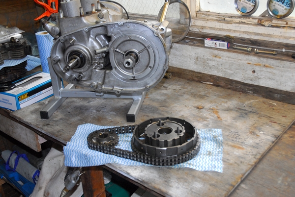 Yesterday morning I changed my mind and 'phoned them. I'd be up later to collect the frame. I arrived around 1 p.m. and happily, the guy had managed to sort my wheels out as well so I could have the lot... goody, goody! After carefully loading everything in the car (I'm glad I've got a big estate car!) and handing over a not inconsiderable chunk of wedge, I headed back south. Everything was bubble wrapped but I unwrapped the rear sub-frame just to see what sort of job they'd made of it and I happy to say they've made a very good job of it indeed. The finish is superb, much better than I'd expected given the rusty condition it was in when I left it with them. I'll leave the frame wrapped and stored in the back room for the time being as I've started work on the engine. I'll finish that first and start putting the chassis back together when that's done.
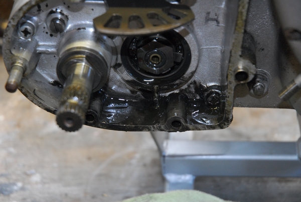
The 'puller' that I needed to get the sprocket off the crankshaft arrived a couple of days ago so it was a simple task to remove the primary drive completely. On further examination, I've decided to replace the clutch friction plates after all. The rest of the primary drive is in such good condition, it doesn't really make sense to put back worn clutch plates. With the primary drive removed, I removed the final drive sprocket cover plate. The 6 slotted screws had been assembled with thread sealer and needed a little persuading with the impact driver to remove them. With the cover removed, the tab washer tapped back and the nut undone, the sprocket was pulled off the gearbox output shaft with the puller I'd used earlier on the engine sprocket. After the trouble I had with the gearbox oil seal on the Bonneville, I'll replace the one on the T90 as a matter of course but I'll remove it when I've stripped the gearbox. That just about finishes the dismantling on that side of the engine. Time to turn it around and start on the other side.
 Having turned the engine around, I can either start on the gearbox or the timing chest. Both have to be dismantled and quite honestly, it doesn't matter in which order I do them so I'll start with the gearbox. First off, the kickstart lever and gear change levers were taken off their respective shafts. That gave clear access to the two nuts and four screws that secure the outer cover. The two nuts and three of the four cross head screws were no problem but the fourth screw was a bitch. Even the impact driver only succeeded in distorting the head and rendering a screwdriver useless. Ok... not a big problem. Some careful drilling with successively larger drills and the head came off without a mark on the aluminium casting. That done, a gentle tap with a plastic faced mallet to break the joint and the outer cover came off without further dramatics. There was some very fine black 'goo' in the bottom of the case. Not sure what it is or where it's come from but it doesn't appear to be metallic so I'm not overly worried. It has been accumulated over nearly 50 years after all. With the cover removed, I had access to the oil feed and return pipes and the nut that secured the oil manifold to the crankcase. It's a tight fit for a spanner but fortunately, the nut wasn't too tight. With that out of the way, the inner gearbox cover could be removed. The two extra screws that secure the inner cover came out easily, which was good. With those removed, another gentle tap with the plastic mallet and the whole gear cluster came out in one assembly, attached to the inner cover. It looks to be in remarkably good condition. There are no broken or chipped teeth on any of the gears and the engagement dogs are smooth and undamaged. The bearings look and feel fine and the thrust washer is barely polished. There's no excessive play in any of the bushes in the gears and the profiles in the selector plate don't appear worn in any way. All of which is more good news.
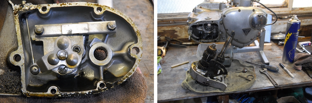
Tuesday, 12th July, 2016
A few 'odd jobs' to do today. First, take the valves out of the cylinder head. That was straightforward enough but I discovered that the valve guides were very worn. They would definitely need replacing, which in turn meant that the valve seats would need to be re-cut. Oh bugger! I could probably replace the valve guides but reaming them to size for the valve stems and re-cutting the seats would be problematic as I don't have the tools to do it. When I re-built the Bonneville, I sent the head to SRM Engineering in Wales. They did a good enough job but they did the lot... skimmed the head, replaced the exhaust valve seats, put thread inserts in for the plugs, new valve guides and they also supplied the valves and new springs... The bill was horrendous. I needed a simpler (cheaper) option for the T90 so I gave T & L Engineering in Elstow a call. They did some very satisfactory work for me on the Guzzi Le Mans. Yes, of course they could replace the guides and re-cut the seats. They would fit 'Colsibro' valve guides which are machined from an alloy of copper, nickel and silicon but they would need the valves so that they could ream the new guides to the exact size. The old valves probably were re-usable but the stems were showing scuff marks and the exhaust valve sealing faces were pitted. On top of that, as mentioned earlier, the end of the stems were worn where the rocker works against them. Bit of a 'no-brainer' really... Four new valves are now on order as is a set of valve springs. When they arrive, I'll take the lot over to T & L. They will vapour blast the head to clean it so I'll let them have the rocker boxes and inlet manifold to blast at the same time. The rocker boxes were still as they came off the bike so they would need to be dismantled. Simply a case of undoing the dome nut on the end of the rocker spindle and tapping the spindle out. No problem there, fortunately.
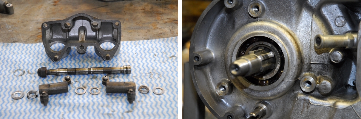
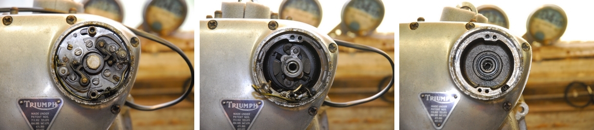
Having sorted the cylinder head and rocker boxes out, it was time to carry on with the engine. First job today was to remove the old crankshaft oil seal. That gave up without a fight... easier than I expected. That accomplished, the next task was to remove the timing cover but the ignition points and automatic advance unit would have to come off first and they are driven by the exhaust camshaft. The points cover was secured by two screws which came out easily. The contact breaker plate was similarly held and that also came off easily. The AAU was held by a central bolt and a tapered joint into the end of the camshaft. With the bolt removed, a gentle sideways tap released the taper and the AAU was removed.
Thursday, 14th July, 2016
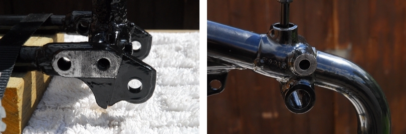
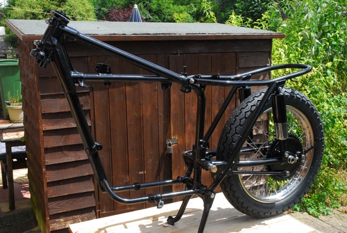
I started the re-assembly today. First I had to clean the powder coating off the points on the frame and rear sub-frame where they bolt together. This needs to be a good, metal to metal joint. It was easy enough with a small sanding drum on the Dremel. That done, the swinging arm was assembled to the main frame. That was just a case of greasing everything up, lining everything up and pushing the spindle through. The rear sub-frame had to be attached next as the swinging arm spindle bolts locate through that. A stud and two nuts at the top and two bolts, one each side at the bottom. With that loosely assembled, the two large swinging arm bolts were screwed into the ends of the spindle and everything tightened up. The swinging arm moved freely without any detectable play... just as it should be with new bushes and spindle. I turned the frame up-side-down then so that I could attach the centre stand. I had new pivot bolts, nuts and tab washers for that as the old ones were very worn and there was a lot of play in the pivots.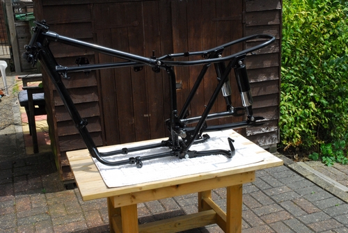 I forked out for a new stainless steel spring as well. It's much easier to attach the spring first and then wrestle the stand into position to bolt it up rather than bolt it up first and then try to get the spring on. Actually, it wasn't too difficult to achieve. One last thing to do and that was to bolt in the new rear suspension units. They fitted nicely and don't look bad either. New stainless steel bolts and washers and stainless 'Nyloc' nuts were used. The bottom pair fully tightened, the top pair just loosely assembled at this stage as those bolts also hold the rear mudguard supports which will be fitted in due course.
Friday, 15th July, 2016
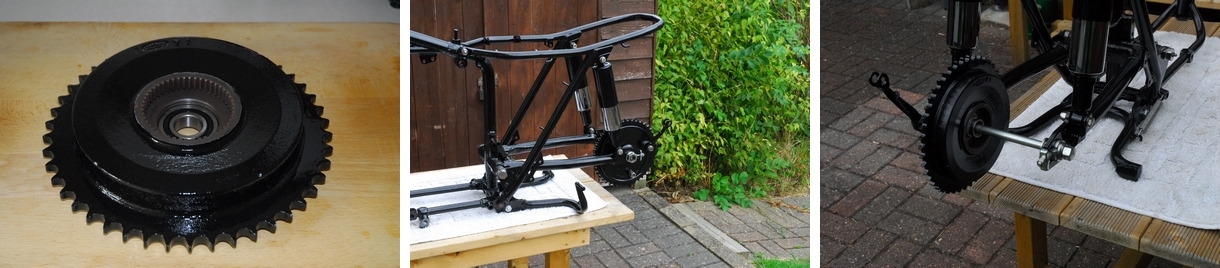
A simple task today... Put the QD sprocket / brake drum back together. The new brake drum bearing had been consigned to the freezer over night so this morning the brake drum went into the oven at 100° Celsius (or Gas Mark 1/4, if you're that way inclined) for about half an hour. Nicely cooked, it was placed on a wooden board and the cold bearing dropped into the recess. It needed no force and settled into it's correct location with a slight hiss.
While that was cooling, the rear brake plate was re-assembled. The old rear brake shoes were completely shot so I assembled it using the shoes that were in the front brake as they had a lot of lining left. I've bought new shoes with modern, high friction, non-asbestos linings for the front brake. By the time I'd sorted that out, the drum had cooled down enough for the bearing axle and grease retaining shims to be installed. The assembled brake plate was fitted and the whole shooting match offered up to the left hand rear fork. New stainless steel chain adjusters and a stainless axle nut complete the assembly. I'd sourced a new rear wheel spindle and spacers. They aren't stainless but they are bright and shiny zinc plated... They'll look good, at least for the time being, anyway!
Saturday, 16th July, 2016
Only time to do a couple of jobs today but on the face of it, they should have been simple enough. First job... Fit the rear brake torque arm. You may remember that I had a spot of bother removing the screw that held the forward end to the swinging arm. I had to use a propane torch and take it up to almost red heat before I could get it undone. The female thread in the swinging arm looked ok but the new screw wouldn't look at it. It was 3/8" x 26 t.p.i. (British Standard Cycle thread). I had a look in my 'tap box' and came up with the right tap... but it was a cheap carbon steel item, not a proper high speed steel one and it didn't look too sharp. It was Hobson's choice, however as it was the only one I had. Suffice it to say that an hour later, minus some knuckle skin and in a foul mood, I had a thread that the new screw was happy to be associated with. The torque arm was now in place.
Last job for today... Put the rear wheel in. First I had to put the new bearings in the hub. As with the brake drum bearing, the new wheel bearings had spent the night in the freezer so they were as small as they were ever going to be (things shrink when they get cold... don't they, fellas). The hub was heated up to spit sizzling with a hot air gun. The bearings dropped in and were located against their register with the minimum of force. That done, it was just a case of offering it up to the brake drum and sliding the new spindle through with the new spacers in place.
Sunday, 17th July, 2016
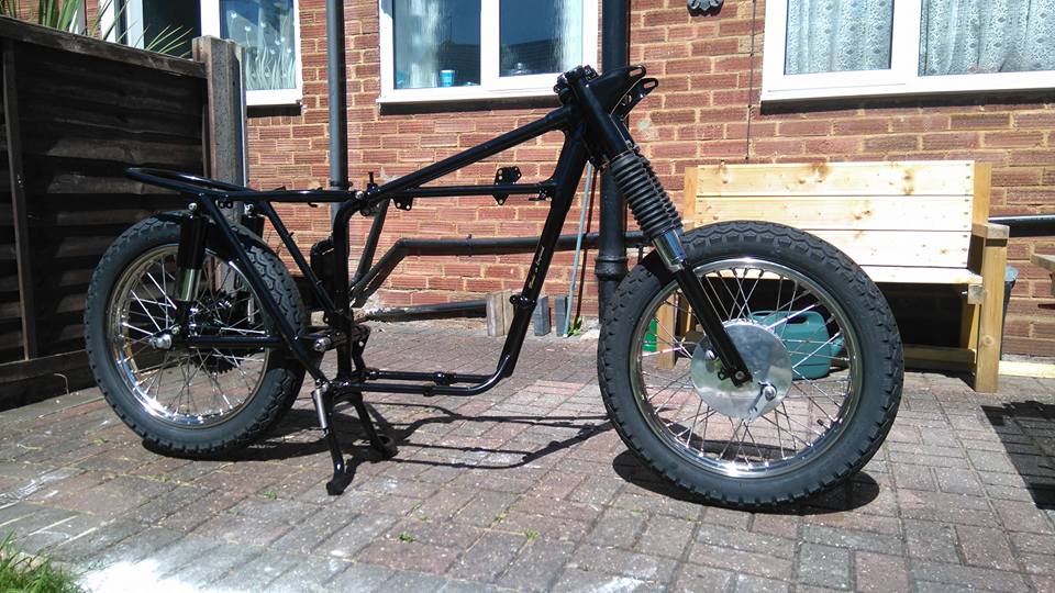
The bike was looking a bit 'unbalanced' so the task today was to build up the front forks. For once, the job was easy and trouble free. The fork legs were built up with new sintered bronze 'Oilite' bushes and new oil seals. I'd also splurged out on a pair of new chrome oil seal covers. The lower sliders had been powder coated black and with new rubber gaiters to cover the springs they were looking like new. The whole job only took about an hour but it was an hour well spent.
Monday, 18th July, 2016
Summer has come at last and today was very hot with temperatures into the low 30s. Not a day to be sweating your socks off, working on a T90 but that's what I was doing... at least until lunchtime when it really had got too hot to work outside. This morning's task was to assemble the fork legs into the upper and lower fork yokes. There was some work to be carried out on the top yoke first. New 'metalastic' bushes for the handlebar mounts had to be pressed in and the new steering lock fitted. Not difficult tasks, once I'd cleaned all the powder coating out of the relevant orifices. They should have been masked off before spraying but weren't! Now to assemble the forks. On the face of it, not a difficult task but it wasn't without its problems. The fork stanchions are a slide fit through the lower yoke and are clamped in place with a pinch bolt. The problem was that the pinch bolt also held the top shrouds that cover the stanchion between the yokes. Without the pinch bolt to clamp the leg, the spring stopped the leg coming up far enough through the shrouds to reach the top yoke. Simple answer... Put a bar through the wheel spindle location at the bottom of the slider and use a small ratchet strap to raise the sliders and compress the springs. Easy, when you think about it. With the top yoke in place and the shrouds over the fork legs, the pinch bolts could be inserted and tightened enough to clamp the stanchions. Job done. Now the forks could be offered up to the frame. Oh yes... Got to put the steering head bearings in first. The original bearings were the older style with a lot of loose balls. I replaced those with the later pattern taper roller bearings. With the bearings in place, the fork assembly was offered up to the frame and the bearings adjusted to give free movement without any 'play'. For the moment, the large cap nuts that secure the fork legs into the top yoke are only finger tight. I have to put a third of a pint of oil into each leg. This give the hydraulic damping action. I had assumed that they would need the same oil as the Bonneville. That used automatic transmission fluid (ATF) of which I had an ample supply. On checking the manual, however, I found that the recommended oil is a straight SAE30 mineral oil of which I had none. Oh bugger! A quick trip to Halfords was singularly useless as they only stock modern multigrade oils. I did manage to find a supplier on the net who will send me a litre of Castrol XL, which is a straight 30 oil. Should be here on Wednesday.
Tuesday, 19th July, 2016
Another very hot day... The hottest so far this year, according to the weather forecasters... So I only worked for a couple of hours this morning. It was time to put the front wheel back together. As usual, the new bearings had been in the freezer overnight and were nicely cooled. The wheel hub was heated with the hot air gun and the whole lot went together fuss-free. The brake plate was re-assembled with the new brake shoes I mentioned earlier and that was fitted to the drum with a new stainless steel nut. That done, it was simply a case of offering it up to the front forks and tightening the bolts securing the fork caps. With the wheel in place I used the peg spanner to finally tighten the chrome fork oil seal holders as I was only able to do them up hand-tight until the bottom sliders were secure and unable to rotate. I now have a rolling chassis and it's actually starting to look a bit more like a motorcycle now.
Tuesday, 26th July, 2016
Things have moved on... The Castrol XL arrived on schedule and the correct amount (190ml) has been added to each fork leg. The new chrome cap nuts are now fully tightened. The front and rear mudguards have been fitted. That takes about ten seconds to type but took me an awful lot longer to achieve. Rhetorical question time... Why is it that holes in components that lined up perfectly before I took the bike apart aren't even close to lining up when I come to put it back together? Ho hum... Anyway... The mudguards and all the brackets and stays that are associated with them are now in place and secured with new stainless screws, nuts and washers. As the wiring for the rear light assembly actually runs along the underside of the rear mudguard, protected by a bolted on steel pressing, that part of the wiring had to be installed before the mudguard was fitted. No big deal as it's only three wires... rear light (brown/green), stop light (brown) and ground return (red). Originally there were only two wires as Triumph (and most other manufactures at the time) in their wisdom used the chassis and other assorted steelwork as the earth (ground return). This led to all sorts of electrical problems and made for generally unreliable electrics.... the blame for which was often erroneously placed in Lucas's ball-park. As I did on the Bonneville, I will include a 'proper' return wire, connected directly to the positive terminal of the battery, for all electrical circuits. You know it makes sense! Talking of rear lights... This one now illuminates a new black and silver period number plate... All perfectly legal as the bike pre-dates the 'orrible yellow reflective things. It also uses the approved character font for the digits.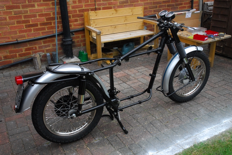
The steering damper has been fitted. That's the big, black knob in the middle of the steering head. No sissy hydraulic damper on this bad girl... just screw the knob down and go for it! (As the Actress said to the Bishop). New rubber bushes have been pressed into the instrument mounting plate and the plate bolted to the top yoke. It gives a little flexibility and reduces the likelihood of engine vibration damaging the tachometer and speedometer... or so they say. The instruments have been given a fresh coat of black gloss and attached to the mounting plate. Next item on the list was the ignition switch. This was cleaned, tested and passed as functional. That has now been installed in the headlamp mount on the right hand fork shroud.
New handlebars have been fitted. The more knowledgeable amongst you will recognise the pattern as 'Norton Straights'. The Tiger 90 is a feisty little lightweight and deserves bars that give a sportier riding position than the American influenced high rise bars that Triumph specified would give. Believe me... they will look right when the bike is finished. Last thing... the front brake has been connected to the new ball-ended lever with a new cable that almost... but not quite... fitted. It only required a minor tweak to the clevis fork at the bottom and all was well.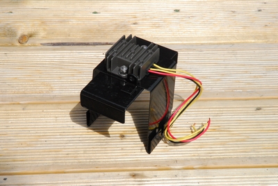
Thursday, 4th August, 2016
It's been a week since my last confession and I have sinned. I haven't spent as long as I would have liked working on the T90. Having said that, thing have moved on a little. As far as the rolling chassis goes, the oil tank on the right and the side panel / tool box on the left have been fitted, although the side panel will probably have to come off again when I start the wiring. A solid state rectifier / regulator has been fitted to replace the plate rectifier and Zener diode that Triumph originally fitted. This will hopefully ensure that the new AGM battery that I've bought will be kept fully charged by the alternator. It should be more reliable, too. The device has been attached to the underside of the battery tray. It's out of the way there but will still be in the cooling airstream. The battery tray has now been fitted to the chassis. That goes under the seat, behind the oil tank. The only other additions to the chassis are the rear chain guard and the headlamp assembly.
There's been a little more action on the engine front. The barrels have been de-rusted and given a coat of 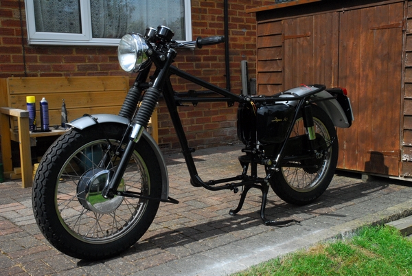 high temperature black engine paint. They look quite smart now. They've also been honed lightly to break the glaze in the bores which will help the new piston rings to bed in quickly. Talking of piston rings, a new set of L.F. Harris rings have been sourced and the end gaps checked. They all need slight adjustment to bring the gaps within the 0.010" - 0.014" specified in the manual. They will be fitted to the pistons in due course. I've spent quite a while polishing up the engine covers... They are the primary chain case, timing cover and gearbox outer cover. They were all first de-greased and given a good going over with 400 grit 'wet & dry' to remove scratches and oxidation. I set up the buffing wheel on the bench grinder and using a stitched mop and medium compound the covers were give a rough polishing. That done, the soft mop was put on and the covers given a final polishing with fine compound. They've come up really well considering what they were like and I'm pleased with the result. That's all for now, Father. I'll see you again after my next transgression.
Sunday, 7th August, 2016
I've gone as far as I can, now, with the rolling chassis until I get the engine back in but there has been an unforeseen delay. I had originally thought that the final drive sprocket would be OK to use but having cleaned it up, I can see that there is too much wear and it will need replacing. No big deal in the great scheme of things but until I get the replacement, I can't re-assemble the gearbox and that is the next job on the engine. In the meantime, I've been back to T & L Engineering to pick up the cylinder head. That now has new valve guides and the seats have been re-cut. It's also been vapour blasted (along with the rocker boxes and the inlet manifold) and looks very smart. It was only half an hours work to install the new valves with the new valve springs and the head is now ready to bolt on. That won't be completed until the engine is back in the frame. It took a little longer to re-assemble the rocker boxes. It was a pain in the butt getting the 'Thackeray' washers correctly located at the end of the rockers and keeping them in place while the spindles were pushed through. Then I discovered that the full engine set of gaskets I'd bought didn't include the sealing 'O' rings for the rocker spindles. Fortunately, I had a 'selection box' of 'O' rings that contained some of the correct size.
I've finally made a decision about the ignition set-up I'm going to use and I've ordered a Pazon "Sure Fire" system. It's a relatively in-expensive analogue system and comes with a 7.1/2 year warranty. An odd number but who's arguing. I couldn't really justify spending big bucks on another C5 digital system like the one on the Bonneville. I'm sure it will do the job nicely. So... that's about it until the new rear drive sprocket arrives.
Friday, 12th August, 2016
There's been a bit of phaffing about in the early part of this week. The new sprocket arrived along with a few other bits I'd ordered. One of the bits wasn't correct so that had to go back and only one ignition coil turned up. I'd ordered two but when the supplier checked them before despatch it was discovered that one was damaged so they gave me a quite generous refund. A second coil has since been sourced from an alternative supplier. The Pazon ignition system turned up on Tuesday and I spent a while sorting out exactly where it's going to be fitted and making sure I have enough of the correctly coloured and rated cable to build the wiring harness. Originally, as I've up-rated the headlamp to a 60/55 watt quartz halogen unit, I had intended to use a pair of simple make-break relays but lack of a suitable mounting for two has meant a change of plans and I've decided to use a single change-over relay. That has meant a modification to the circuit that I'd originally laid out. No big deal at this stage. It's easy to make changes before any wires are actually installed.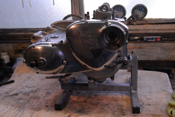
Wednesday was a 'lost day' as far as bike building was concerned. Les and I went to the Great British Beer Festival at Olympia. Needless to say, not much was done yesterday, either. Today, however, was much more productive. The new final drive sprocket was installed onto the top gear out-put sleeve. The old sprocket took considerable effort to remove so I was expecting the new one to be a tight fit as well. As it happened, it was a comfortable slide fit and went on without effort. A new tab washer was fitted and the retaining nut fully tightened. That done, it was time to reassemble the gearbox. The was easier than expected. All the internals are assembled onto the inner cover and the whole lot offered up to the crankcase in one lump. The mating faces were 'painted' with ThreeBond 1184 sealant and the inner cover, with the gearbox already assembled on it, slid into place without any drama. The two inner cover screws held the whole lot in place while I checked that all gears were correctly sequenced. They were.
There were a couple of small jobs to do before the outer cover went on. The first an easy one... bolt the oil feed and return pipe manifold to the crankcase with a new gasket. The second, slightly more difficult... fit the kickstart return spring in the correct position. I lost a little skin before I realised that a screwdriver could be used to hold the spring in position instead on my fingers... Ho hum! With the spring secured, the outer cover was slid over the two mounting studs and secured with new stainless socket screws. New stainless dome nuts and annealed copper washers finished the gearbox. All that there was left to do on this side of the engine was to put the timing cover back on. I'd already installed a new oil seal so it was just a case of painting some sealer on the joint faces and screwing in the eight new stainless screws. Job done!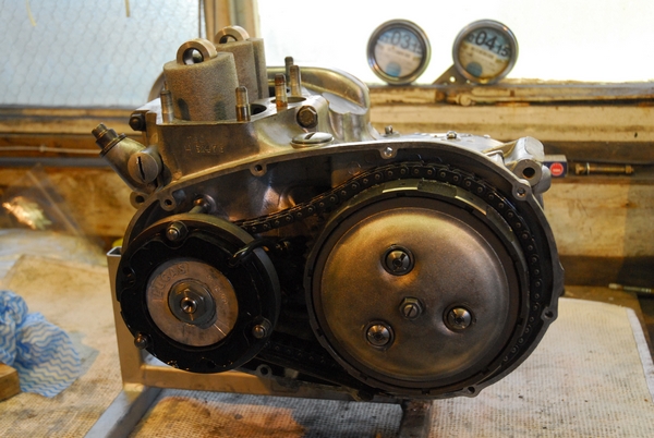
Time to turn the engine around and reassemble the primary drive. I'd already fitted a new oil seal to the crankshaft main bearing so there was only the cover over the final drive sprocket to fit before assembling the primary drive. That had a new oil seal as well and was secured with 6 screws. The clutch basket, primary chain and engine sprocket all have to be installed at the same time as the duplex primary chain is endless and has no joining link. It's not as difficult as it sounds and it all went together nicely. The clutch was secured onto the gearbox mainshaft with a new locknut. The chain tensioner blade was next in. I can't actually adjust the chain until the primary chain case has been fitted so that's a job for later on. The three alternator stator mounting studs were screwed in with a little blue Loctite and the alternator rotor fitted to the mainshaft. I've put a new tab washer under the rotor nut but I've not folded it over yet for a good reason. I'll be using a socket spanner on that nut to rotate the engine when I set up the ignition timing and I can't do that if the tab washer is folded over. Once it's all set up, I'll bend it over the nut. The alternator stator was next and that mounted on the three studs I put in earlier. The output cable was fed out through the rear of the chain case and secured under the engine with a 'P' clip. That will be connected into the wiring harness later.
Earlier in the week I'd cleaned all the oil off the clutch plates with white spirit so they were ready to go back in. The pressure plate was last on... having remembered to put the clutch operating pushrod in first. I've used new clutch springs so hopefully, with clean plates and new springs, there will be no clutch slip. That was it for today. Next job is to put the pistons and barrels back on. That can wait until tomorrow.
Saturday, 13th August, 2016
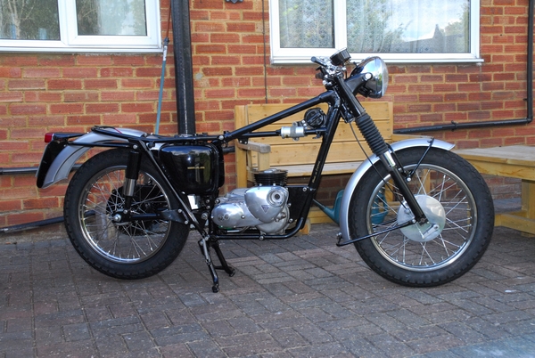 It's now tomorrow; time to finish off the work on the engine and get it ready to go back in the frame. First job... put the new rings on the pistons, hopefully without breaking any of them. That was carefully accomplished. I used the hot air gun to warm up the pistons enough to let the gudgeon pin slide through the connecting rods and secured them with new circlips. Now it was time to put the barrels back on. A new cylinder base gasket was fitted over the studs first... before I forget it. The cam followers were re-installed into their original locations and held in position with two rare earth magnets. That will stop them falling into the crankcase while I'm juggling with the barrels. A pair of wooden dowels were slipped under the pistons to hold them level while I lowered the barrels over them. It's just a case of compressing each piston ring in turn whilst gently lowering the barrels over them. Sounds complicated and it would have been easier with three pairs of hands, but it all goes to plan and the barrels drop smoothly onto the crankcase studs. New 12-point nuts were used and the barrels tightened down onto the new gasket. The magnets were removed from the cam followers and that was as far as the engine was going to be built up before putting it back in the frame... and that was the next task.
This engine isn't as heavy as the Bonneville's 650cc lump so it wasn't too difficult to drop it into the frame single handedly. I wrapped the bottom frame tubes with bar towels to protect the paintwork and lifted the engine into place. The rear mounting lined up perfectly so I pushed the stud through to keep the engine in place. A small 'jack' was placed under the engine to lift it up enough to line up the bottom mounting hole. The stud and spacers were popped into place and that just left the front mounting plates. They went on easily and then all the fixings were fully tightened... That was it, the engine (or most of it) was back in the frame. One final job was to put the new final drive chain on while I still had reasonable access to the gearbox sprocket. That was accomplished without any undue stress and the rear wheel roughly aligned. It will need aligning properly in due course.
Sunday, 14th August, 2016
With the bottom end of the engine back in the frame, it was a good opportunity to set up the new Pazon electronic ignition system. Not as simple as it sounds as there is nothing to indicate the correct 40° B.T.D.C fully advanced position that the Pazon requires. There is an engraved line on the alternator rotor but no pointer to line up with it in the chain case cover. That wasn't introduced until the following year of manufacture, so I had to do it the 'old fashioned way' with a dial test indicator (DTI) set up on the top of one of the pistons.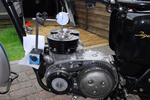 If you know the crank angle, the crankshaft stroke and the length between centres of the connecting rod (all of which are in the workshop manual) it's simple geometry to work out linear distance of the piston travel that equates to 40° of crankshaft rotation. I'll not bore you with the maths but trust me... it's 0.367". The workshop manual actually says it's 0.360" but I'm not going to argue over 7 thousandths of an inch. So... I set up the DTI on it's magnetic base and stuck it onto the front engine plate. This allowed me to set it up on the centre (near enough) of the piston. The engine was rotated backwards and forwards to obtain a 'maximum' reading on the DTI.
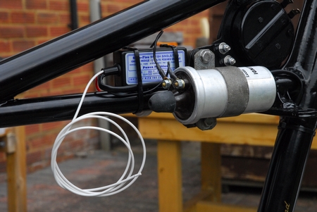 This would be Top Dead Centre (T.D.C.) and the DTI was zero'd. Rotate the engine backwards until the piston had travelled more than 0.360" and then rotate it forward until the DTI reads exactly 0.360". That will position the crankshaft exactly 40° before T.D.C. - where it needs to be to set up the Pazon trigger unit in the timing cover where the old contact breaker points were once located. The trigger unit fitted perfectly and was set according to the instruction sheet that Pazon supplied.
The 'Black Box' is small enough to fit in the frame 'triangle' between the two new 6 volt Lucas ignition coils. I ran a bead of black silicone sealer along the frame and secured the box onto it with a couple of cable ties. Once the sealer has cured, the box will be secure and won't fall off!. That done, the coils were connected up to the Pazon unit. It's a 'wasted spark' system. The two 6 volt coils are connected in series and they both fire simultaneously each revolution of the crankshaft so one of them actually fires the spark plug on the exhaust stroke each time. The two trigger wires from the Pazon box were fed through a length of sleeving and run down the front frame tube to the trigger unit in the timing case. That just leaves the white wire to connect to the ignition switch when I make up the harness.
Monday, 15th August, 2016
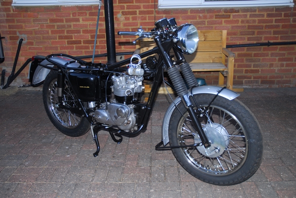 I had a thought while I was enjoying a quiet pint yesterday evening... In the great scheme of things, there's not actually a lot left to do. So I started a little earlier this morning as it promised to be a very hot afternoon. Glad I did... First job this morning was to reassemble the top end of the engine. Simple enough but not without some difficulty getting the four inner rocker box / cylinder head bolts past the frame top tube. I'd taken the engine out with the head and rocker boxes in place. I assumed that they could be replaced with the engine in the frame. Assumption is the mother of all cock-ups. I did, however, manage to juggle the bolts back without having to remove the engine again... just!!! With the top end re-assembled and the the new stainless bolts tightened up to the correct torque, it was time to set the valve clearances. There's no easy way to get a feeler gauge in easily so the best alternative is to tighten the tappet up until there is no clearance, then back it off the required amount to give the correct clearance. That's 0.002" for the inlet valves and 0.004" for the exhausts. It's a 26 t.p.i. thread so 1/16 of a turn is approximately 2 thou and 1/8 of a turn will be 4 thou.
I'd bought a set of new screw-in rocker box caps from Motao for the Bonneville but couldn't use them as they fouled the twin carburettors. As the T90 only has a single carb, they fitted with perfectly. Nice. The inlet manifold was attached but as yet the new Amal Mk 1 Concentric carburettor that I'd ordered a month ago hasn't turned up. A quick phone call to Burlen to get an update confirmed that it wouldn't be available for another three weeks... Bummer.
The new oil feed to the rockers was installed and connected to the oil return pipe on the oil tank. The last thing I did today was to fit the new clutch cable. That involved a fair bit a 'fettling' to the nipple on the gearbox end to make it fit. Then having got that sorted, I found that the cable outer casing was just a trifle sort and I had to use all the adjustment at the lever to take up the slack. That's not a satisfactory state of affairs so I've had to order an optional longer 'adjustment sleeve' for the gearbox end to take up some of the slack. Ho hum....
Monday, 22nd August, 2016
Once again things have moved on... not that there's much to see at first glance. The biggest step forward is the wiring. I've completely wired up the bike from scratch. With the change from plate rectifier and Zener diode regulator to an integrated solid state rectifier/regulator, the addition of a Pazon electronic ignition system and fitting a 60/55w halogen headlamp unit that required a relay to be fitted you can appreciate that the original harness was no longer applicable; even if it was in a useable condition... which it wasn't. The wiring has been tested and is working as it should. One other change I've made is that the lights are now only available when the ignition is switched on. I had a habit of switching off the ignition and forgetting to turn off the lights. That can't happen now.
The old hard plastic engine breather pipes have been replaced with nice shiny flexible black 'Tygon' tubing which is much nicer. The speedometer and tachometer drive cables have been re-installed and the problem with the clutch cable has been sorted with the optional longer adjustment sleeve. The gearbox has been filled up to the correct level with EP80W/90 'GL-4' gearbox oil and so far appears to be oil-tight (not that I expected any leaks but you never know!). One problem I did unexpectedly encounter was with the oil tank. I'd put it all back without the feed pipe filter installed... Another duff assumption on my part was that the filter would be removable for cleaning with the tank in position. It isn't... The designer needs a bollocking for that mistake. So I had to remove the battery, battery carrier and rear engine plates before I could remove the oil tank again and install the filter. I have no intention of going through all that rigmarole every time I change the oil so I've ordered an oil filter kit that will be installed under the gearbox and uses a replaceable, screw-on cartridge filter. That will do a better job of keeping the oil clean and be a lot less hassle to change. I've put the dual seat back on and with it, a new retaining strap (bit of wire, really) that stops it opening too far.
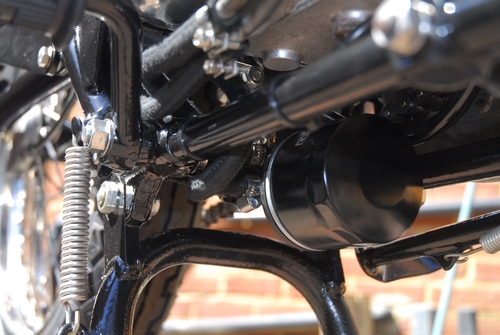
Tuesday, 23nd August, 2016
Don't you just love it when a plan comes together... and don't you just hate it when it all goes to poo? That's a hypothetical question so there's no need to answer. Today should have been a nice, stress-free hour or two in the workshop cleaning up the old carburetor as the new one I ordered won't be ready for another two or three weeks. I was halfway through that when the postman delivered the new oil filter kit that I ordered yesterday.... That was quick!! I had spent some time yesterday talking to the supplier on the telephone before ordering the kit and I was assured that each kit was tailored to suit the specific bike model and installation was quick and easy... Yeah, right. It took me two hours, a lot of fiddling about and modifying brackets to make it fit but it's now on... tucked away neatly under the gearbox. So back to cleaning the carburetor. That all went OK, no problems there. I bolted it onto the manifold and connected the two new cables I'd bought. One for the air slide (or 'choke', if you prefer) and another for the main slide. They fitted the carburetor perfectly but would they connect to the choke lever and the twist-grip... would they buggery. In both cases the inner cable was too short. By about an inch for the choke cable and about 1/2 an inch for the twist-grip cable. Now this really pissed me off more than somewhat. They weren't cables that I'd bought off some dubious supplier on the internet, I'd bought these from a well respected and long established classic motorcycle shop in London when I visited them to buy some other stuff. I'd given them the model, the year and the frame number and they even looked up the part number but they still didn't fit. Well you can't lengthen the inner cable but you can shorten the outer sleeve which achieves the same result so that's what I had to do. Another hour or so with the Dremel fitted with a fine grinding disc cutting through the steel outer sleeve being very careful not to damage the inner cable. Got the cables fitted and working eventually.
Saturday, 27nd August, 2016
That's it, then. The job's a good 'un. I've been putting the final touches to it over the last couple of days. The primary chain case was put back and the chain tensioned. The exhaust system, footrests, rear brake pedal and operating rod were all bolted back together. The fuel tank was finally put on and bolted down.... Time to see if it was worth the effort so yesterday late afternoon, I put 5 litres of Shell premium petrol in the tank and crossed my fingers. The carburetor was tickled and the engine kicked over once with the ignition off. Switch power through to the Pazon ignition system and kick it over again... The little beauty fired immediately and ran. A small tweak to the air screw and throttle stop was all that was necessary to achieve a smooth(ish) tick-over. A quick check to make sure the oil was returning to the tank and that there were no obvious leaks. It was and there weren't. Switched her off while I sat and just looked at her. Best go for a ride then, so she was pushed out onto the back access road while I donned my crash hat and jacket.
Turned the petrol on again and it flooded out of the float bowl all over the road... Bugger!!. Took my jacket and hat off again and stripped the float bowl off the carb. I had wondered about the old white plastic float and metering needle when I cleaned the carb a few days ago but thought it would probably be OK until the new carburetor arrived from Amal. It obviously wasn't so they were changed for one of the later 'Stay-up' floats and a Viton tipped aluminium needle which I happened to have left over from the Bonneville rebuild. Put it all back together and voila... no more leaking. A largely uneventful blast up the A505 dual carriageway to Hitchin, back via Hexton and Lilley followed. The only problem was that the chrome cover on the left side of the front hub came adrift, probably because I hadn't secured it properly, and the clutch cable needed a little work and adjustment. So... that was yesterday.
I was up early this morning and brought the bike up from the garage. First off... the front hub plate was secured properly and the locking tabs tapped over to keep it in place. The clutch cable was adjusted and the lever moved slightly to give a more comfortable feel. The oil level was checked and a drop more added. Finally, I washed and polished her. It's the last Saturday of the month so it coffee and cakes at The Two Wheel Centre later this morning..... a good opportunity to show her off. It's taken about 14 weeks, start to finish and more than a few of our fine English 'quids' but I'm very happy and satisfied with the result. Bring on the next one....
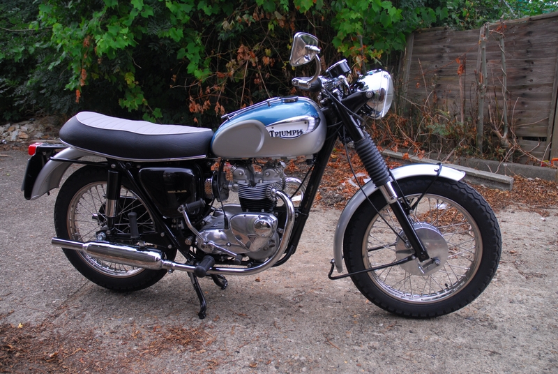
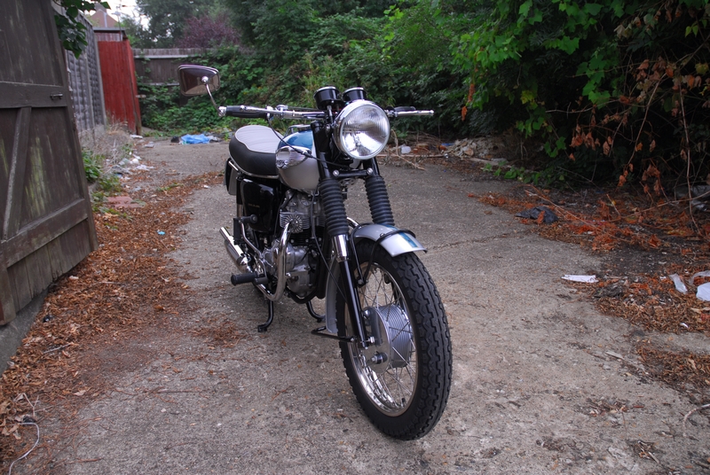
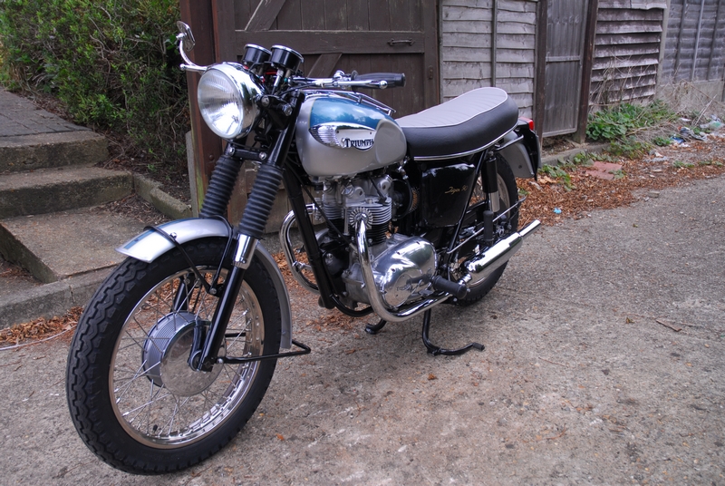
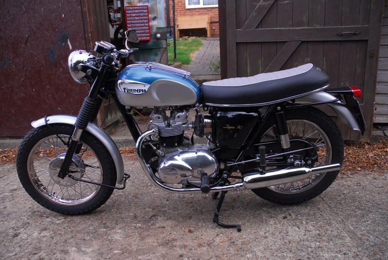
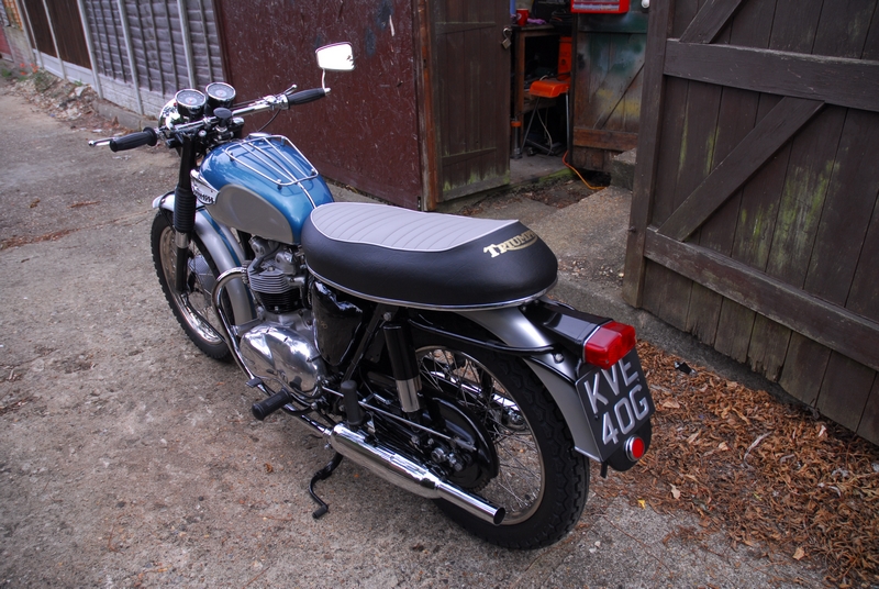
Having put more than a few miles on the clock, I have to say that the little T90 is one of the nicest bikes I've ever ridden. I just love it to bits. It does, however, have one almighty problem... The front brake! Over the last little while I've done everything I can think of to improve the performance of that 7" single leading shoe (SLS) brake; all to no avail. It does slow you down and stop you eventually, but the thought of having to use it in an emergency it just downright scary!
So... what to do? I had hoped to keep the bike as near to original as possible but I also want it to be safe. With that in mind, I've managed to locate and buy a second hand twin leading shoe (TLS) front brake plate as was fitted as standard to the early 1970s 500cc "Tiger 100" machines. As I may have mentioned up the page somewhere, the T90 and T100 share a lot of the chassis parts and the later TLS brake plate will be a straight swap for the SLS plate. The plate has been sent up to CWC for preparing and powder coating in the same 'Hybrid Silver' as the hub. I've had to buy all the other parts, shoes, springs and linkages etc. and they are all new. The external linkage is all polished stainless. Hopefully, The plate will be back from CWC soon and I can put the whole lot together and fit it. Stay tuned.....
Some time later...
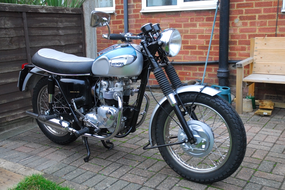 CWC let me down a little on this one. Not having heard anything from them for a couple of weeks, I gave them a call. After waiting on 'hold' for a while, the lass at the other end came back and told me that the brake plate was all done. I arranged for them to post it back to me but a week later, it still hadn't arrived. Another 'phone call ensued. After another wait, the lass came back and said it was still in their despatch department. I told them I would come up and collect it as I didn't want it caught up in the Christmas postal fiasco that comes every year at this time. So that's what I did.
I'd already got the other bits and pieces I needed so it was just a case of putting it all together. That went without a hitch and today I installed it on the bike. It took a little while before I was happy with the linkage adjustment. I needed to be sure in my own mind that both shoes were in contact with the drum equally. It all looks remarkably fine... but the proof will be the next time I take it out onto the road. As they've started salting the roads now, that won't be until next spring.
Some time later still... Spring 2017
It's the middle of March and the weather, in patches, has been good so I woke Lilly up and we've been out a couple of times. No great distance but far enough to know that the TLS front brake is in a whole different league to the old SLS brake. Right now, it's powerful enough to squeal the front tyre if applied with some determination and it's only going to get better as the shoes 'bed in' properly. I'm well pleased with the result and don't begrudge spending the not inconsiderable amount of money it cost. Bring it on.....
Lilly's story will continue. As is the way with old motorcycles, Lilly will "evolve" and her continuing story will be told in "Part 2".
Link to Index and Home Page.
Link to Triumph Bonneville T120R page.
Link to AJS M18S page.
Link to Matchless G3/LS page.
Link to Matchless G80CS page.
Link to Honda VFR750 page.
Link to Norton 650SS page.
Last updated 27/08/2022