I'd been looking for an AMC heavyweight for a while but I always seemed to be too late. Whenever I spotted a likely one for sale and phoned I got the "Sorry, mate, it's just gone!" answer. One Sunday afternoon in March, 2016, I spotted one advertised at a classic bike dealers in Suffolk that was exactly what I was looking for and their website still had it as 'For Sale'. I pitched up at their premises at the quoted opening time of 9 a.m. the next morning to find the place all locked up. It was a unit on a farm so I wandered round and asked in one of the other units. I was told they don't usually turn up until 9:15. I waited... until 9:50 when a guy turned up and unlocked. "Hello, been waiting long?" he asked. "Since 9" says I. "Oh, we don't usually open until 9:15 on a Monday." I looked pointedly at my watch... "Would that be 9:15 GMT or 9:15 Suffolk time?" I could tell he wasn't amused. I asked about the Matchless G80S he had advertised only to be told that it was already sold. I mentioned their website. He told me that it only gets updated when 'the girl' has time to do it which wasn't very often, apparently.
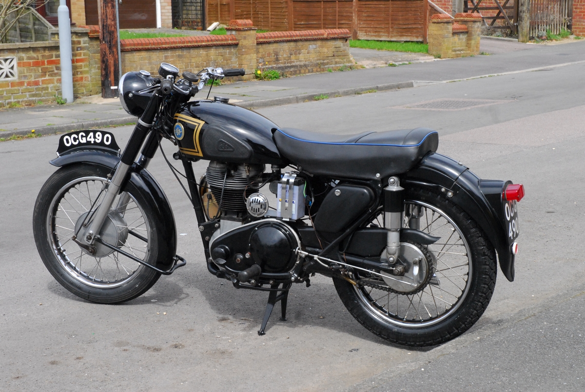
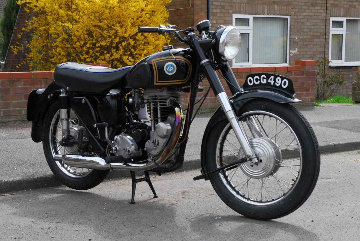
Anyway... When I got back home I had another browse around the classic bike websites and a new advert had popped up. It was a classic vehicle dealer in Cornwall. They had a 1955 registered AJS Model 18S advertised so I phoned them and this time I wasn't too late. They had only just taken it in part exchange for an old MG sports car. The story I was told was that it had belonged to an elderly bloke, a long standing customer apparently, who restored it but never rode it. They told me it was first registered in 1955. It was in great condition, they said and didn't need anything doing to it. Hmmm....
I chatted to them for about half an hour and then agreed to buy it. The owner of the dealership said that his son was coming up to London on the Thursday and would delivery the bike. Splendid. Well.... to cut a long story short, it never turned up. A family emergency meant that the son never came up to London apparently, but should have phoned me to let me know. In fact, it was 5 weeks before I eventually set eyes on her. On a test ride, they found the clutch was slipping so they ordered a complete new clutch and that caused the delay.
It was old enough to be exempt from both Vehicle Excise Duty (road tax) and M.O.T. but you still had to go through the formality of taxing it (at no cost) as a Historic Vehicle. Therein lay the first problem. When the bike was delivered we did the 'Change of Ownership' thing with the V5C registration document and I was given the V5C/2 'Green Slip'. The dealer sent the old registration document back to the DVLA in Swansea. Now, in theory, as I had already arranged insurance, I should have been able to 'tax' the bike on-line but that failed. Where the taxation class should have been 'Historic Vehicle', on the V5C/2 is was 'Vehicle Not Licensed For Road Use' and that chucked up an error when I attempted to tax it. I phoned the DVLA. A very helpful guy at the other end explained that 'Vehicle Not Licensed For Road Use' was an old way of preserving the original registration number. Before the days of 'Statutory Off Road Notice' (SORN) if a vehicle wasn't taxed for an extended period, the registration number was 'taken back' by the DVLA and effectively lost. If the vehicle was subsequently put back on the road, the owner would have to apply for a new 'age related' number but he wouldn't get back the original one. To prevent that happening, if you had no intention of using the vehicle on the road, (as the last owner of the AJS had after he 'restored' it) you could change the taxation class to 'Vehicle Not Licensed For Road Use' and that would preserve the registration number and prevent it being taken away by the DVLA. All it meant was that I had to apply to change the taxation class to 'Historic Vehicle' and that I could do at the local Post Office. Well... almost!! I downloaded the necessary forms, filled them in and took them, with the insurance certificate to the Post Office. The guy behind the counter took the forms, bashed about on a computer keyboard, gave me a receipt for £0.00 that stated that my AJS was now 'taxed' for the year. Good oh!
In due course I received the new V5C document from Swansea, with me as the new registered keeper.... and the taxation class as... you've guessed it... 'Vehicle Not Licensed For Road Use'. Bugger!! Another phone call to the DVLA and after a bit of explaining, I was assured that another new V5C would be issued. All the paperwork was there... the original V5C, my change of class form and the post office receipt. It's just that they all arrived at the same time and the 'Change of ownership' was completed (without change of class) first. I did get the correct V5C in the post a few days later and for a time, at least, all was well in my world.
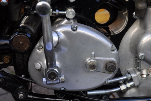
A few days later... Having made the bike 'Road Legal', it was time to try it out. It was wheeled up from the garage for a check-over... oil level, tyre pressures, stuff like that. It all seemed to be ok. When I tried to start it, I discovered the first problem... The kickstart lever went down easily but it wasn't turning the engine over. The clutch was slipping big time. There was a little free-play in the clutch cable so that was ok. I guessed what it was straight away. Whoever had rebuilt the clutch, hadn't the first idea how to adjust it and had set it up incorrectly. To be sure, I needed to take off the inspection cover on the primary drive case. That's when alarm bells started to 'tinkle'. The cover should have been held in place with eight 2BA screws. Six were in place, one was missing completely and the last was an oversize self tapping screw. So much for a 'restoration'. Anyway... the clutch had been replaced as the friction plates were all new but it just hadn't been set up properly. You need to do things in a particular order so I started at the beginning. The five nuts holding the springs were all reset to the same position... flush with the pressure plate as a starting point then 'tweaked' individually to ensure that the pressure plate lifted evenly all the way round when the clutch lever was operated. That accomplished, the cable was slackened right off to ensure that the operating mechanism was free to find it's 'home' position. That done, the pushrod adjusting screw lock nut was undone and the adjusting screw in the pressure plate was backed off and then screwed in again until it was just touching the pushrod and there was no 'free play'. At this point it was backed out 1/2 a turn and the lock nut tightened. Finally, the inspection cover was replaced and the cable was adjusted to leave about 1/8 of an inch free play. Mission accomplished. The clutch was correctly adjusted and the kickstart now turned the engine over with no sign of slipping. 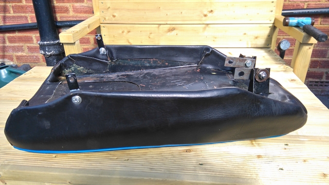 I managed to get the engine started... eventually. There's a very definite technique to starting these big singles and it'd been a long time since I last started one... my old Norton ES2 'Café Racer' back in the early 70's. A short run out was in order which proved quite successful. The bike ran nicely and what's more... it was fun. As intimated earlier, the 'restoration' that was supposed to have been carried out by the PO wasn't all that good and there were a few other problems. The seat was obviously not correct as it was bolted in place with some very non-standard strips of steel. It turned out to be a seat from a newer 'light weight' model, apparently. I had recently joined the AJS and Matchless Owners Club (AMOC) so I 'phoned their spares department in Kettering. They had the correct seat in stock so I drove up there to collect it. The old one was subsequently sold on eBay. It was when I came to fit it that I discovered the next problem. The front of the seat was bolted to the frame by utilising the large stud and nuts that secured the rear sub-frame to the front main-frame. That stud was smaller diameter than it should have been and was loose anyway. A new stud, nuts and washers were also acquired along with the two chrome plated rear seat fixing screws.
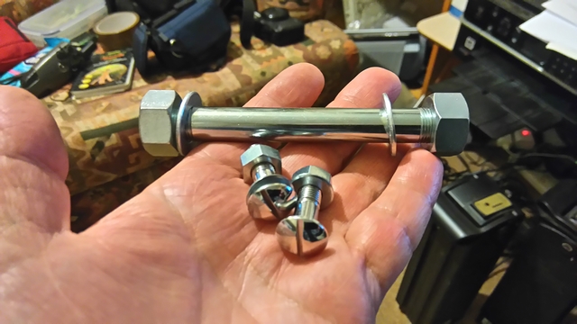
That sorted out the seat. It was starting to look better. Another short ride and another problem discovered... the battery wasn't being charged. With the lights on and the engine running, the ammeter was still showing a significant discharge. Oh bum!! It's been a while since I'd worked on an old D.C. dynamo system as most bikes use the more efficient A.C. alternator but I still remembered a thing or two, fortunately. A quick check proved that the dynamo was pushing out around 30 volts at modest engine revs which should have been more than enough. It was the old style Lucas MCR-2 mechanical regulator that was badly adjusted. A few minutes with a screwdriver and a digital multi-meter and we had the system charging... and then we didn't again. The regulator just wasn't playing ball. If you've read my Bonneville and T90 pages, you'll know that I'm not passionate about maintaining absolute originality. If there's something available now that wasn't available when the bike was built and does a better job, then I'm quite happy to use it. That's how come a new, solid state, DVR2 regulator now replaces the old mechanical job. The battery is now being charged and the ammeter no longer shows a discharge with the lights on. One more problem solved.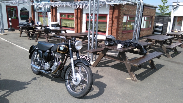
I was now happy to take Bess out for a longer ride so a trip up the A5 trunk road to "The Super Sausage" transport café, just south of Towcester was planned... not that it took a lot of planning. I dumped 10 litres of premium petrol in the tank and headed north. Bess behaved herself, we got there and back again without any problem. It was after we got back that a serious problem developed. The next time I brought her out of the garage and started her, she was smoking rather badly... and the smoking got worse until I couldn't see across the road. Oh dear!!! The fault was fairly quickly diagnosed. Oil was being pumped to the engine from the oil tank but it wasn't being returned. It was just building up in the crankcase. This was most definitely NOT GOOD. There were a number of possible reasons why the oil wasn't being returned, most of which revolved around the oil pump(s). I'm not going to go into any great technical detail but from the looking at the design of the pump, it would be a reasonable assumption that if the feed pump is working and it's effectively the same pump that returns the oil, then the return pump should be working too. It obviously isn't so there must be something else. A blockage in one of the pipes, internal or external, or an air leak into the return side of the pump are the best bets. Of course... correcting it isn't easy or straight forward... it never is, is it?
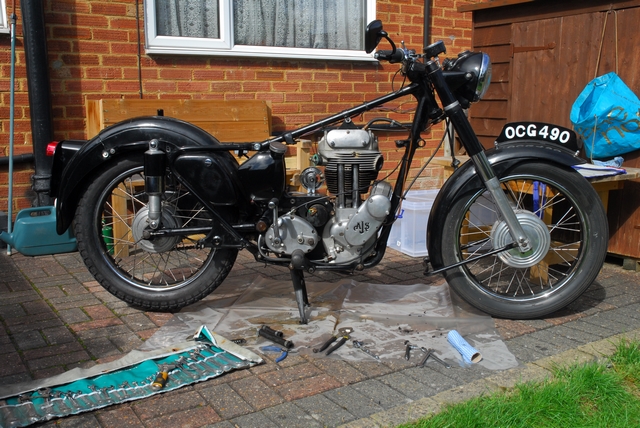
A Monday in the middle of September, 2016. Bess was currently being 'stored' in a lock-up about 3/4 of a mile from the house and to do any work on her, she needed to be at home. I wheeled her out, drained the oil from the crankcase, topped up the oil tank and rode her home. She had just started to smoke again by the time I got there. So far, so good. I brought her up to the only area where I can work on bike at home and made her secure until I could start working on her.
Some Time Later... I took the filter out of the oil tank. There was a significant amount of aluminium debris in the filter. That is not good news. The oil tank was drained and the oil pipes from the tank to the engine were checked. They proved to be dirty but certainly not blocked. Cross that off the list. Time to look at the oil pump. It was then that I realised that again, a PO had made life difficult for me. The cover plate on the return end of the oil pump had been put back with incorrect screws and it must have been done with the engine out of the frame as there was no way to get them in, or out, with the engine in the frame. "Oh dear" says I... or words to that effect!
I sat with a cup of coffee and weighed up the options. Not that there were any. If I wanted to get to the oil pump... which I did... the engine would have to come out of the frame. In the end, you accept the inevitable and just get stuck in. It wouldn't be the first engine I've taken out of a frame and I don't expect it will be the last... although at 70 years old, I hope there are not too many more!
 OK... time to get the show on the road. The first bits are easy, remove the seat, tank, carburettor and exhaust system. Remove the footrests complete with the square section rod that they are mounted on. So far, so good. The primary drive was next. The sealing band around the chain case was taken off and the rubber seal removed. That dumped a lot of oil into the tray I'd thoughtfully placed under the bike. The nut in the centre of the chain case was undone (more about that later) and the outer cover removed. Now it was time to get mucky and strip off the clutch, primary chain and crankshaft shock absorber. Therein lay the next problem... I couldn't undo the nut on the end of the crankshaft. I'd almost considered the ultimate answer... the angle grinder... when a suggestion was put to me. Find someone with an air impact gun. I didn't need to find anyone... there was one in my shed that friend Les had given me a few weeks ago and I'd forgotten all about. The air hose was brought up from the shed, the compressor cranked up to 150 p.s.i. and the air gun connected. The nut was instantly undone... What a result.
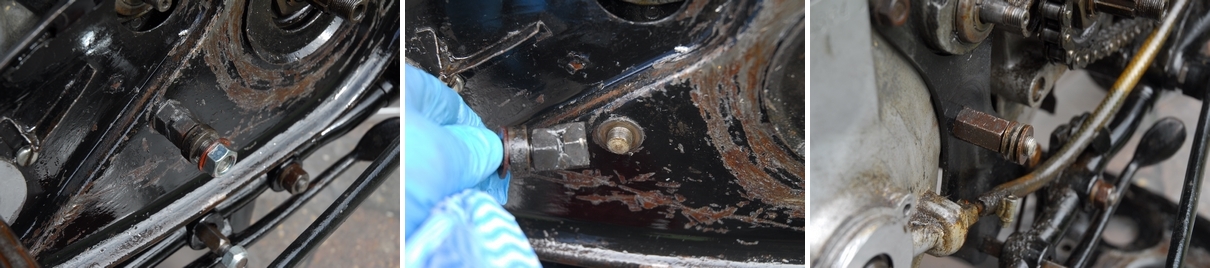
 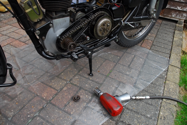 Having got that nut undone, the clutch springs were removed and the plates stripped out of the clutch drum. I expected that there would be some wear in the drum and I was right but at £200 for a replacement, it's going back... at least for the time being. It may get replaced in due course. The clutch centre nut was undone and removed, along with the tab washer. They had both suffered at the hands of a PO and will be replaced. The dynamo sprocket and drive chain were next so that the primary drive sprocket could be slid off the crankshaft. Another problem... there should have been a spacer behind that sprocket and that was missing completely. That had allowed the dynamo chain to come into contact with the boss on the crankcase and wear a groove in it. Not serious, in the great scheme of things but annoying, never-the-less. A new spacer will be put back when the bike is reassembled. OK... that brings me back to the chain case mounting stud that I mentioned earlier. That, along with its associated spacers and nuts had been assembled in completely the wrong order. The spacer that should have be fitted between the left hand rear engine plate and the inner chain case half was in fact fitted on the other side of the engine between the nut and the right hand rear engine plate. This, in effect, meant that the stud was no longer long enough to attach the chain case outer cover and the PO had welded two nuts together and added another short length of studding to make up the difference. Sometimes, you just gotta laugh at the sheer ineptitude of some bike owners. Fortunately, all the bits are there and will be put back in the right order when I reassemble everything.
 It was fairly obvious, from the cleanliness of the cylinder head, that the engine had not had a lot of running since being rebuilt. It was also obvious that three of the rocker box bolt threads had been stripped and repaired at some time in the past. More evidence of a 'ham-fisted' PO, I'm afraid. However, the repairs had been carried out satisfactorily and I'm quite happy about them. This is, in fact, where the alloy swarf that was in the felt oil filter came from. One of the repairs at least had been carried out with the engine in situ as there was still some more swarf on top of the cylinder head and in the pushrod tubes. The pushrods could now be lifted out and it was with a little surprise and pleasure to discover that they were actually brand new. Unlike most of the other nuts on the machine, the adjusting nuts on these pushrods were pristine. The four cylinder head bolts were undone, a little at a time until they were all loose. This avoids the possibility of the head warping as the bolts were undone. The head was lifted off and surprise, surprise...
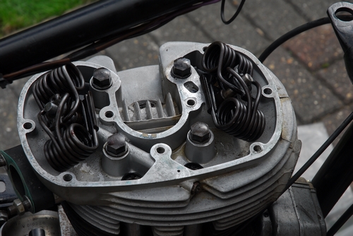
 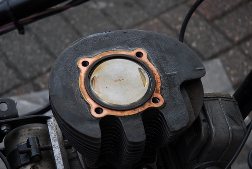 There was a brand new shiny piston in the barrel. It was stamped "+0.040" which would indicate that the cylinder had been rebored by that amount. The rebore, however, had been carried out at some time in the past and was not recent. I measured the bore with an internal micrometer and although it was a little worn, it was within serviceable limits. The valve springs are of the somewhat unusual 'hair-pin' design. Quite common on older bikes but not much used, if at all, today. The valves look like they have been replaced recently and the combustion chamber is relatively clean. It all points to the engine being rebuilt recently (in terms of engine running time).
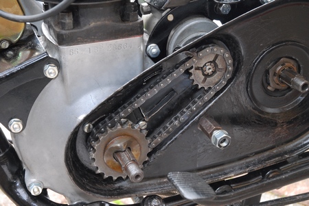
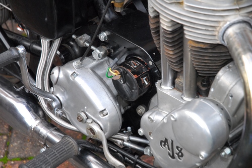
With the head and rocker box removed, the next item on the agenda was to remove the magneto. That entailed undoing the six screws holding the drive cover in place and then removing the drive chain and sprockets.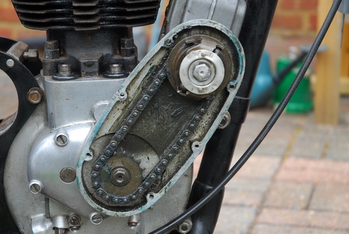 The sprocket on the magneto was incorporated into the centrifugal automatic advance unit and that was self extracting... just undo the centre bolt and the AAU and sprocket are drawn off the magneto shaft. The magneto is driven off the exhaust camshaft and the sprocket was on a taper secured with a nut. That came off easily enough and the drive chain, complete with sprockets and AAU was removed. With the drive out of the way, the five screws holding the timing cover in place were the next to go and the cover removed. The inlet and exhaust cams were also taken out as there was now nothing holding them in place. The dynamo was also removed. This was only held in place by a clamping band. The bolt was slackened off a few turns and the dynamo slid out. (More about that, later, too). The magneto, with it's mounting plate, spacers and front engine
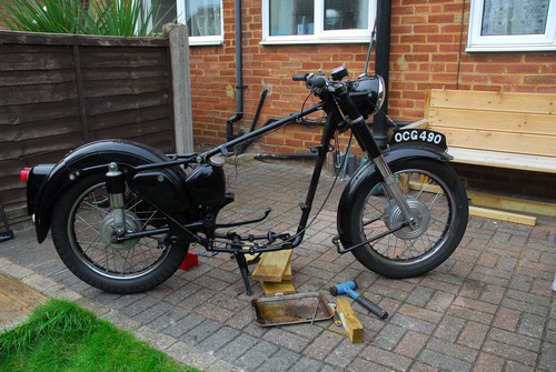 plates were removed after first undoing and removing the three studs that held them all in place. With all the ancillaries out of the way it was then just a matter of removing all the remaining studs and engine plates. The final drive chain was disconnected and the gearbox removed first. That just left the engine and that was lifted out and taken into the workshop (my shed, really).
With the engine up-side-down on the bench, it was easy to get at the oil pump. I'd already taken off the end plate at the feed end of the pump as that had the pipe up the to rocker-box attached. The end cover at the return end was the one I was interested in. Of the four (incorrect) screws that secured it, two were loose, one was tight and one was stripped. Not a recipe for a working pump. It would be easy for air to be sucked in here by the pump which would stop the pump lifting oil from the crankcase. Hopefully, I've found the problem. Having removed both end covers, and the guide pin, the pump plunger was slipped out of it's bore in the crankcase. Both the plunger and the bore were in very good condition with no sign of undue wear. Good news... The three blanking screws in the oil drill-ways were removed and the drill-ways checked for blockages. I didn't find any. They were squirted through with solvent brake cleaner and then blown through with compressed air.
Some thoughts... While the engine and gearbox are out of the frame and the side tool boxes are away being painted, I'm thinking it may be a good opportunity to take a look at the wiring. As I mentioned up the page a ways, I've already fitted a solid state regulator so that's a start. The battery was completely knackered and will need to be replaced anyway and quite honestly, the wiring is a 60 year old mess. Like most machines of the period, it uses the frame and other assorted metalwork as the 'ground return' which is, quite honestly, the reason for so many electrical failures on old machines. This bike has a 6 volt 'positive ground' system but it's very basic. The dynamo and battery are only there to supply power for the lights... headlight, tail light, speedometer light and brake stop light. The ignition is supplied by the magneto and completely independent. The dynamo doesn't care whether the bike is 6 volt or 12 volt as it will supply current at up to 30 volts quite happily. The faster it spins, the higher the voltage and consequently more current it produces. It relies on the regulator to do exactly that... regulate. The solid state regulator I've fitted is 'switchable' from 6 volts to 12 volts so I could quite easily change the system to 12 volts. The downside is that the engine would need to rev a little higher before it starts charging so it's 'swings and round-a-bouts'. Whichever way I choose to go, the bike needs to be rewired and have a proper harness made instead of the loose collection of wires that presently connect the lights to the battery and switch. My current line of thought is to keep it 6 volts and to use the latest generation of LED lamps. I already use 12v LED stop/tail lamps in the two Triumph rear lights and they are impressive... very impressive. A 6 volt version and an LED headlamp as well could be the answer for Bess. The current drain would be less and the relatively small battery would have an easier life. I'll give it some more thought.
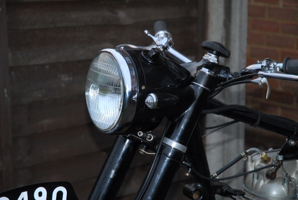
Tempus has fugit'd and little progress has been made. I've had a week living in a houseboat on the River Bure in Norfolk. The general idea was to catch a few pike and drink a few pints of local ale. Mission accomplished!!. The stripped thread in the crankcase has been repaired. I contacted a guy in Maidenhead who specialised in thread repairs on vintage machinery and he had a supply of 3 B.A. 'Heli-Coil' inserts, one of which now resides in the stripped hole. The oil pump can now be re-assembled and hopefully it will all work as it should. I've been in touch with another member of the AMOC and he has a spare '55 headlamp shell and is willing to swap it for the '53 shell that is currently fitted to Bess. That will bring her back to somewhere near the correct specification for her year. I may put off rewiring her until I get the replacement headlamp sorted. It's all taking a little longer than I expected and it looks likely that she won't be back on the road before they start spraying grit and salt. Not to worry, I'll take what time I need to over the coming Winter and hopefully she'll be ready for the Spring.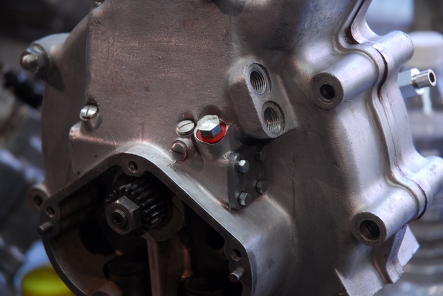
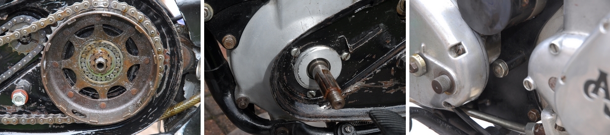
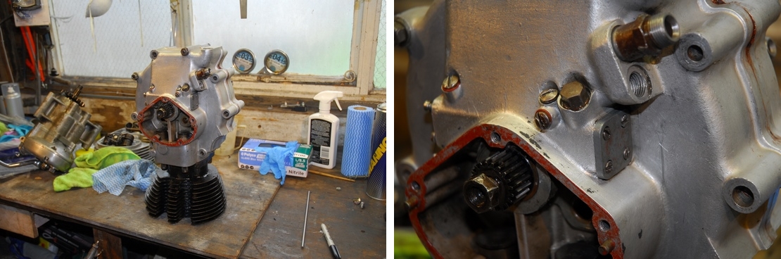
The taking apart has finished... hopefully, and the putting back together has started. Having repaired the stripped thread in the crankcase, it was time to put the oil pump back together. The worm drive on the crankshaft and the helical gear on the pump plunger were undamaged so the plunger wasn't replaced. The bore in the crankcase was smooth and free from any scoring so there's no reason why the pump shouldn't now function perfectly. The bore was given a final clean, the plunger coated with clean engine oil and the one was slipped into the other... perfik! Although the original guide pin appeared undamaged, that was replaced with a new one along with a new retaining screw and fibre washer. [EDIT IMPORTANT... After receiving a phone call from Ken DeGroome, the fibre washer has been removed from under the guide pin retaining screw. Apparently, this reduces the engagement of the guide pin in the pump plunger and can lead to excessive wear and ultimately catastrophic failure.] At that point, the crankshaft was turned over a number of time to check that the pump plunger moved as it should. I'm happy to say that it does. It rotated and oscillated in the approved manner. Three new stainless steel blanking plugs with new fibre washers were screwed into the oil-ways and the end plate put back with a new paper gasket (and a smear of Hylomar gasket sealant). This time, it's secured with the correct hex-head screws which will make it easier to remove in the future, if it needs to be, without having to take the engine out of the frame. 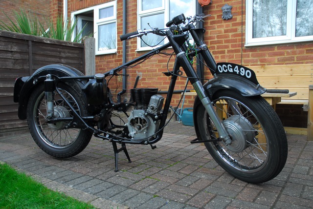 If you compare the two photos above, you'll see the difference. You may also notice that the chewed up nut retaining the crankshaft pinion has also been replaced... If you're ever unfortunate enough to have to work on one of these engines, be aware... that nut has a left hand thread.
That was all that needed to be done to the engine at this point in time... Next job was to drop the engine back into the frame... tricky!! The frame is made up of half a dozen or so separate components and most of them seem to be attached to each other by the studs that also hold the engine in place. Those studs have to be removed to enable the engine to be taken out and of course... the frame goes 'boing' and springs apart. Trying to get the new studs back in while holding the engine in place and coercing the frame tubes back into position with only two hands is certain to give you hours of fun. Needless to say... it was accomplished with the minimum of swearing and only a little knuckle skin lost. Having finally managed to get the engine located by the bottom mounting stud, the front engine plates and magneto were the next items to go on. At this stage, the nuts were only done up 'finger tight' as I may need a little movement when I come to put the gearbox and rear engine plates back... but that's a job for another day.
The aforementioned headlamp swap has failed to materialise. The gent that suggested it in the first place couldn't find the bits he thought he had... but... at that very moment, another AMOC member advertised a complete '55 headlamp for sale on the forum. I jumped in straight away and a deal was struck. A handful of our great British quids jumped electronically from one bank account to another and the new headlamp is on it's way to me, courtesy of the Queen's Royal Mail. Hooray...
In preparation for the new headlamp, I decided to have a look at the front forks today. It had been a source of annoyance that the fork shrouds that support the headlamp rattled about between to top and bottom yokes. There was about 3mm of 'up and down' play that shouldn't be there. Looking at the parts list, there should be thick rubber washers that sits between the bottom yoke and the lower housing for the shroud. They were missing... 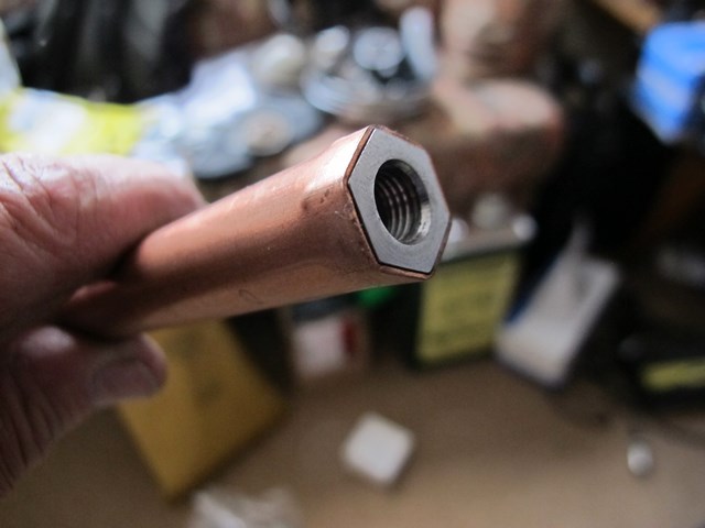 I'm starting to dislike with a passion, the PO who was supposed to have 'restored' this bike. Two new rubber washers had been sourced from the AMOC and today I would fit them. Not a big job on the face of it. Take off the top yoke, slide off the shrouds and their housings drop the rubber washer over the stanchions and pop the whole lot back together again... 20 minutes, maybe... 1/2 an hour at the most, right?... WRONG!!!
The first bit was easy... I put a strap around the bottom yoke and secured it to the frame. This would stop the forks dropping out of the frame (and the 28 tiny steel balls that are the bearing going everywhere) when I removed the top yoke. The first thing I noticed when I undid the two cap nuts on top of the forks was that the damper rods that should have have been screwed into them... weren't! They were sitting about 10 inches down the inside the fork tube. Arrggghhhh.... I carried on and removed the top yoke. It was then that I noticed that one fork leg appeared to be shorter than the other. It transpired that the pinch bolts in the bottom yoke that locked that stanchions in place was not the correct ones (bloody PO). They are hexagon socket screws (Allen screws) and the two fitted had originally been longer. The PO had cut them down with a hacksaw but they were still too long and 'bottomed out' in the threaded hole in the lower yoke before they were tight enough to clamp the fork stanchions. That allowed the fork spring to draw the stanchions down through the bottom yoke when I undid the cap nuts. As a short term measure, the screws were cut down again but new stainless steel screws of the correct length have been ordered from AMOC and will be fitted when they arrive.
Fortunately, I still had the fork assembly tool that I made for the T90 and used that to pull the stanchion back up against the spring pressure and tighten the pinch bolt up properly. Having sorted out that little problem, the new rubber washers were installed and the lower shroud housing dropped on. The top yoke followed after replacing the 28 tiny steel balls and the steering head nut secured everything in place. Now I had to retrieve the damper rods from deep inside the fork stanchions. They had a 5/16" x 26 t.p.i. thread so I made up a simple tool to retrieve them. 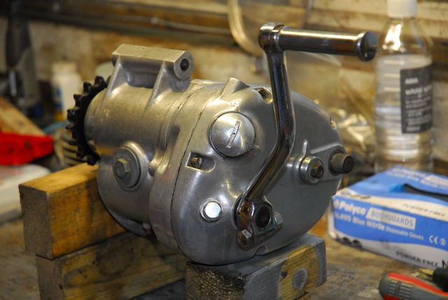 In the true spirit of improvisation, I hammered a correctly threaded nut into the end of a length of 15mm copper plumbing pipe, poked it into the fork tube and screwed it onto the end of the damper rod. I could then pull the rod up and Bob's yer dad's brother. When I checked, there was no oil to speak of in the forks so 6 fl. ozs. of "Castrolite" SAE20 oil was poured into each leg. The damper rods were screwed into the underside of the cap nuts, the lock-nuts tightened and the cap nuts screwed back into place. The job's a good 'un.
Today was wet so I used the time I had available to clean up the gearbox prior to putting it back into the frame. I had no idea when the oil had last been changed so the first job was to drain out the old oil. That looked ok... There was the best parts of the pint that there should have been in there and while it was discoloured, it wasn't 'dirty'. The outside wasn't too grimy and it cleaned up reasonably well with a brush and white spirit. I had noticed that the five slotted, cheese head screws that secured the outer cover were well chewed and the slots showed all the signs being taken out and put back again numerous times.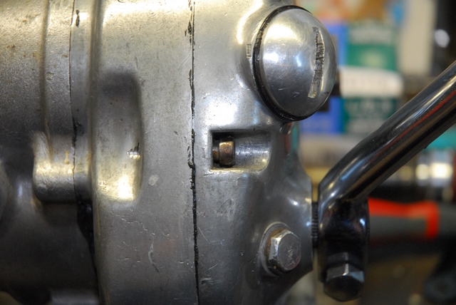 The joints between the gearbox proper, the inner cover and the outer cover had a lot of black silicone sealant around them. There was no evidence that the joints were leaking so I decided to apply the 'If it ain't broke, don't fix it.' mantra and leave well enough alone. That was until I spotted something.... The head of one of the screws wasn't in contact with the outer cover as it should have been; it was a good 2mm clear. I thought that the screw just needed to be tightened but that proved not to be the case. I couldn't screw it in any more so I unscrewed it... Yep, you've guessed... The dreaded PO had used the wrong screw for the job. Again, this was originally a longer bolt that had been cut down and had an unthreaded portion under the head. That effectively prevented the screw from tightening down onto the cover. I'm not going to mess about; there are only five screws so I'll source a new set and replace them all. Why on earth do people 'bodge' things like that? It's so obviously the wrong screw so why use it? Ho hum....
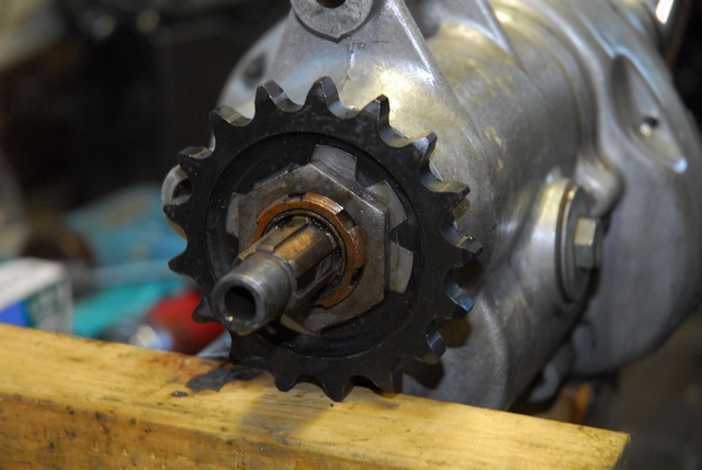
The dealer I bought the bike from told me that he was going to replace the chain and sprockets before he delivered the bike and he'd been true to his word. The 17 tooth final drive sprocket on the gearbox was indeed new, however, he hadn't bothered to replace the tab washer under the nut or, for that matter, tighten the nut properly. It was loose and the only thing stopping it coming undone completely was the old and very second hand tab washer. I'd noticed that when I took the bike apart so I'd already got a new tab washer ready to put back. The nut was undone and the old tab washer replaced with the new one and the nut tightened fully. Two of the tabs were then bent over to secure the nut and stop it coming loose. Finally, a pint of EP80W-90 GL-4 specification gear oil was poured back into the gearbox. That's it... the gearbox is ready to go back into the frame. [EDIT... I found out subsequently, that I should have used a straight SAE50 grade mineral oil in the gearbox. The multigrade oil that I used was what I use in the gearbox of my Meriden Triumph twins. The oil in the Burman box on the AJS is now the correct SAE50]
The new headlamp turned up this morning. It certainly looks the business. 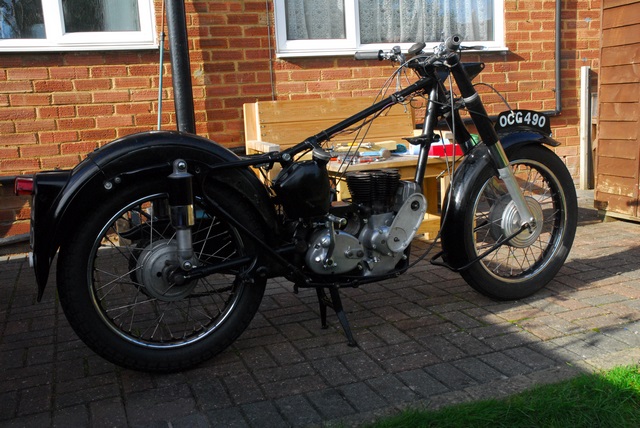 The paint is good and it even has the rubber sealing ring for the speedometer in place. Talking of speedometers, I 'phoned 'Chronometric Instrument Services' in Nottingham and ordered a new flanged bezel, glass and sealing ring for the speedometer. That little lot will allow me to mount the speedo into the new headlamp nacelle. While I was in a 'phoning' mood, I also ordered the new screws for the gearbox outer cover from AMOC. That done, it was time to actually do something on the bike. Re-installing the gearbox was the next task. That went really well and I was quite pleased with myself until I realised that I hadn't fitted the centre stand return spring. I had to undo all the gearbox and engine plate bolts again in order to get the spring orientated correctly... Then it was just brute force and a considerable amount of swearing before it all snapped into place. Once everything was all done up again, I turned my attention to installing and 'timing' the camshafts. Easy enough, really. Just turn the engine until the piston is at the very top of the cylinder and line up the marks as per the picture in the Owner's Handbook. The cams were liberally coated with 'Graphogen' colloidal graphite paste which will keep them lubricated until the oil starts circulating. With the camshafts in place the timing cover was screwed back into position.
The rear chain was wrapped around the sprockets and the back half of the primary drive chain case was put back, this time with the spacer and long nut in the correct place. It doesn't sound like much but that lot took me about four hours. We're getting there... slowly.
 I have to admit, I'd forgotten just how much fun could be had trying to get the ignition timing set correctly on an old Lucas magneto; but more of that later. It was not an early start this morning and the postman arrived before I'd uncovered the bike. Good news... he'd brought me the stuff I'd ordered from Chronometrics and the new gearbox cover screws from AMOC so I started with the new screws. A couple of the old ones were a little reluctant to come out but they all succumbed in the end. The new ones look quite nice... all shiny and un-molested. There were a couple of other jobs to do today; none of them very exciting and I didn't expect any of them to take too long. Hmmm...
The new oil pipes were the next item on the list. They were a little more awkward than expected, mainly due to their location and close proximity to just about everything else around them.... and they weren't quite the right shape. I had to 'adjust' the bend in them before I was happy. I had to modify an old 5/8" Whitworth spanner with the angle grinder to get the clearance I needed to fully tighten the nuts. 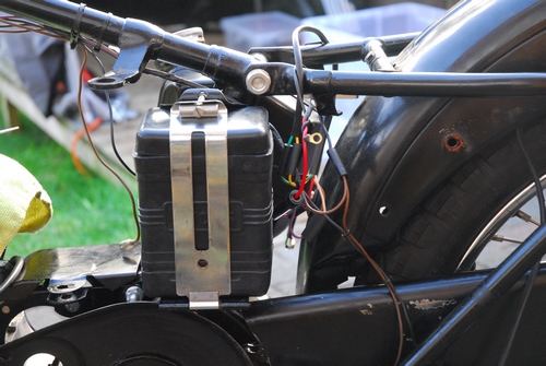 These are only 'short' pipes and are supposed to be connected to the oil tank with rubber hoses. I don't like rubber hoses so I've ordered a pair of nitrile hoses, sheathed in braided stainless steel. They will set it off nicely.
The battery supplied with the bike was a 'wet' lead-acid item of dubious age and uncertain condition that just didn't look right on a bike of this age. That had to go. You can no longer buy the old, black rubber cased Lucas batteries that were originally fitted but you can buy a replica rubber box that mimics the old battery and fit a modern 6 volt, 13 Ah AGM leakproof battery inside it. That's what I've done so the battery carrier was the next thing to put back on Bess. The 'new battery' was fitted and looks the part... Don't worry about the tatty wiring as that will all be replaced with a new harness in due course. The last job I had planned for today was to put on the drive chain and sprockets for the magneto. That meant that the ignition timing would need to be set. According to the Driver's Handbook, the ignition should be set to 1/2" Before Top Dead Centre (BTDC) at full advance. 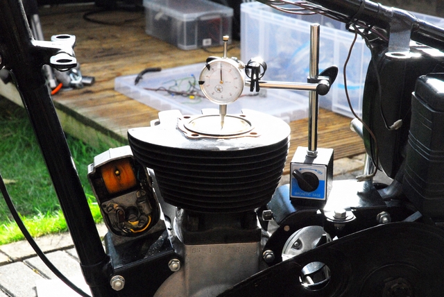 What that means in effect is that the automatic advance unit (AAU) must be held against the springs in the fully advanced position, the piston set to exactly 1/2" BTDC on the compression stroke, the magneto set so that the contact breaker points are just on the point of opening and then tightening the nut that holds the drive sprocket onto the exhaust camshaft. All this, while working on both sides of the bike at the same time and with only two hands. Pretty awesome, eh! Well, no, actually; it's really quite simple if a bit 'fiddly'. A Dial Test Indicator (DTI) was set up on a magnetic base and centred on the piston. The DTI was set to zero with the piston at exactly TDC on the compression stroke. That's with the piston coming up after the inlet cam follower goes down. The engine was then rotated backwards until the piston had moved down the bore more than 1/2" as indicated on the DTI. The engine was then rotated forward until the piston had moved back up the bore to a point where it was exactly 1/2" BTDC as indicated by the DTI. That was the piston set in the correct place. The AAU had already been attached to the magneto shaft and was held in the fully advanced position with a piece rubber. The drive sprocket on the camshaft was left loose so that it could rotate without disturbing the engine's position.
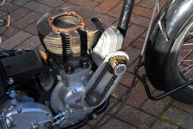 The contact breaker points had previously been cleaned and set to the correct gap. A strip of cigarette paper was inserted between the contact breaker points in the magneto and the magneto rotated anti-clockwise (looking at the points side) until the points were fully closed. That was everything set, ready to start. Now it was simply a case of rotating the magneto drive clockwise until the the strip of cigarette paper could just be pulled free of the contact breaker points and then tightening the drive sprocket securing nut. It took a couple of attempts to get it exactly right but I was quite happy that the ignition timing was now set to the best of my ability, with the equipment I had available to me. I wasn't entirely happy with the way the AAU was working. There was a lot of wear in the bob-weight pivots and the springs didn't seem to return the weights to the fully retarded position as sharply as they might. There's not much I can do about the wear as the whole assembly is riveted together and a new unit seems to be rarer than rocking horse shit... and probably just as expensive. New springs, however, are available and I'll get a pair next time I put an order in to AMOC. Changing them is easy. It won't affect the timing but it may improve the unit's reliability.
 Another week has passed with very little work being done to Bess. Sometimes real life just gets in the way. However, Ernie the Paint 'phoned me a couple of days ago and asked me to go and have a look at the tank. He wanted to make sure that I was happy with the gold lines before he put the final coats of clear lacquer on. I was... it was spot on! Having got that out of the way, it was time to start work again. The oil lines were the next job. Why couldn't AJS use 3/8" bore pipes like the Triumphs instead of the huge 1/2" bore pipes? It would have been a lot easier to get them fitted.
I'd been let down with some 3BA stainless cap head screws that I had intended to use to secure the front oil pump end cap. Checking on-line, it seems that "Stainless Automotive Fastenings" is a bit of a scam website. They have a well documented history of not supplying and not refunding either. I'll just have to chalk that one up to experience... bastards! [EDIT... The screws did eventually turn some 5 weeks after I'd ordered them]. I had the 3BA slotted screws that I'd sourced from AMOC so I used them to put the front end cap back on. They look OK... A light smear of Hylomar on the paper gasket should ensure that it doesn't leak under pressure.
Now it was time to put the rest of the engine back together.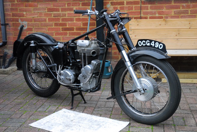 The cylinder head was clean and needed no work other than to insert the new rubber seals for the push-rod tubes. A light coating of "Molykote 111" silicone grease ensured that they were an easy fit into their recesses in the head. Another light coating on the ends of the push-rod tubes and they were pushed into the new seals. New rubber O-rings were fitted around the cam followers to seal the bottom of the tubes, a new copper gasket placed on the cylinder barrel and the head was dropped on. The four bolts were tightened evenly and diagonally and finally tightened with a torque wrench to 38 ft.lb. Time to put the push-rods back in before the rocker box was installed. I mentioned earlier that the push-rods were brand new. That didn't stop one of them having a problem, though. I'd detected a little movement between the aluminium rod and the steel ball fitting at the bottom. A shark tug, and the two parted company. That shouldn't happen... they were supposed to be a press fit. Both parts were thoroughly de-greased and re-assembled with a little "Loctite 638" high strength retainer. They won't be coming apart again anytime soon! With the push-rods in place and the piston set to T.D.C. on the compression stroke, the rocker box was refitted. It's really starting to look a bit more like a motorcycle now, rather than a collection of old bits and pieces. The last item on the agenda today was the new oil feed pipe to the rocker box. The old one was well past it's 'sell by' date. That took a few attempts to get the bends acceptable before it was tightened into place.
 I mentioned a while back that I was beginning to dislike the previous owner who was supposed to have restored this machine. That dislike has turned to positive hatred.... I went out this morning to reassemble the primary drive. An easy enough job, one would have thought. But no... "he" has conspired against me yet again. Before the primary drive could be put back, the dynamo has to be installed because the drive chain for the dynamo sits behind the primary drive chain. I sorted out the parts I'd need and after a few minutes the chain and sprockets were in place and things were looking ok. Then I went round to the other side of the bike... "That doesn't look right." I thought... The back end of the dynamo was hard up against the gearbox. You have to appreciate that to adjust the tension of the primary drive chain, the gearbox is moved backwards or forwards. The gearbox was currently in it's most rearward position and the dynamo was hard up against it. There was no way the gearbox could be moved forward.
 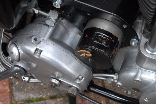 The original dynamo that would have been fitted to Bess was a Lucas E3N which is a shorter variant and made specifically for the AJS and Matchless heavyweight singles. The one I was holding in my hand was the longer Lucas E3L. It was the wrong dynamo for this bike and was in all probability originally fitted to a BSA 650cc A10.
After I'd calmed down a bit and stopped swearing, I spent a fruitless couple of hours on the phone and on 'Google' trying to locate a correct E3N. It seems that hen's teeth are common by comparison. Then I had a little luck... I was given the phone number of a guy named Paul Dunn who, I was told, was probably the only bloke in the country who may be able to help. I 'phoned him and related the story. He turned out to be a veritable encyclopedia of dynamo information and ran a company called "Dynamos, Dynamos, Dynamos". He knew all about the long and short variants and what's more... he could help. If I sent the incorrect E3L to him, he would rebuild it as the shorter E3N with all new bearings, brushes etc. The E3L was on its way to him within the hour. There is a price to pay, of course but I'm not going to bore you with sordid details like that. Let's just say it's not cheap!!
 Good news, bad news and some just plain news. First off... the dynamo. I've phoned Paul Dunn and he has confirmed that my E3L dynamo has arrived safely. He has dismantled it and that's where the bad news starts. The aluminium die-casting that hold the brushes is cracked. Not an uncommon problem, apparently with 60 year old components that weren't of the highest quality to start with. New replacement die-castings haven't been available for decades so there were only two alternatives... Option 1 - look for a serviceable second hand part; now becoming increasingly rare and if I do find one, will it last any length of time before it too breaks? Or... Option 2 - Paul has commissioned a local engineering company to make some for him. These are CNC machined from billet aluminium and are the mutt's nuts. Bit of a 'no brainer' really so Paul will be building up my replacement dynamo with the new machined part... It only adds another 50 of our fine British quids to the bill!! With any luck, I should have the replacement dynamo in a couple of weeks time.
While I've been waiting to put the primary drive together, I've not exactly been idle. I've created and installed a completely new wiring harness with new cables and connectors. As previously mentioned, I now have the correct headlamp for a 1955 bike. What I didn't have at that time was a pair of the Lucas 516 'Torpedo' sidelights that were used to mount the headlamp into the fork shrouds. Fortunately, they were not unique to AJS or Matchless. Back in the day, they were used on everything from the Austin A30 to the XK series Jaguars and fortunately, a lot have survived. I picked up a pair on eBay for a paltry £30. The chrome plating on the rims was excellent but the plating on the bodies was somewhat rougher. That really didn't matter because the lights fitted to the AJS had the bodies painted black. I sanded down the bodies to remove what little rust there was, gave them 3 coats of acid etch primer, 3 coats of gloss black and two coats of clear lacquer. I was very satisfied with the result.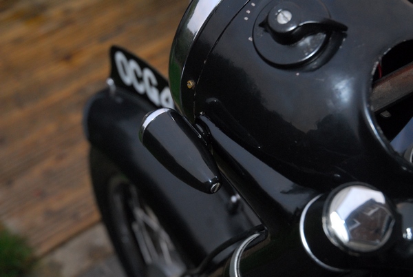 The new flanged bezel and new glass arrived for the speedometer. Getting the old bezel off was no easier than I expected it would be. It's screwed onto the body with a very fine thread and it had been on there for 60 years. It wasn't about to come off without a fight. Chronometric speedometers are quite delicate; working, as the name suggests with a clock mechanism. I really didn't want to damage it by giving it a lot of abuse. A fine fibre cutting disc on the Dremel and some delicate cutting was all that was required. The brass bezel was split and gave up the fight with no damage to the body. I cleaned up the thread with a fine wire brush and applied a smear of light machine oil to the thread. I dropped in the new glass and the new flanged bezel screwed on without any further drama. It was only when I offered it up to the headlamp cowl that I realised that there was still a problem. The rubber sealing ring that came with the headlamp was a bit soft and 'gooey'. That, in itself wasn't the problem... I could get a new one easily enough from AMOC Spares. The problem was the reset knob for the 'Trip' odometer. It was in the wrong place. This speedometer was obviously not intended for use in the headlamp cowl of an AJS. I could install it ok but I'd never be able to reset the trip mileage. A 'phone call to Chronometric Instrument Services confirmed it. It was the wrong speedo. There was good news, however... Yippee. My speedometer could be converted and C.I.S. could do it easily if I sent it up to them in Nottingham. So that's where it is now. Hopefully, it won't take too long although the weather has become decidedly cooler and Autumn is definitely here. Bess probably won't be going anywhere until the Spring, so doesn't really matter too much how long it takes... within reason.
It's November the 5th... Fireworks night and Sheila's birthday. This evening, while I'm typing this, it sounds like World War III has started. Not that that has anything to do with Bess's problems; just thought I'd chuck it in. Today the exhaust pipe went back on. Like a lot of motorcycle engines, particularly older ones, the steel pipe is simply pushed into a hole in the aluminium cylinder head. Time, bad maintenance and careless owners have all contributed to another problem I'll have to sort out. 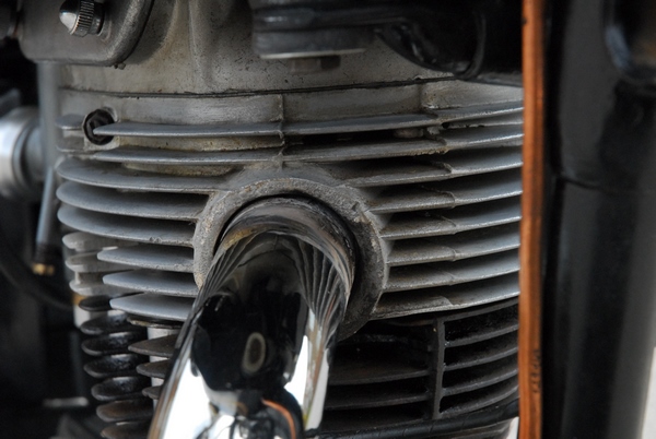 The exhaust port in the soft aluminium cylinder head has worn and become enlarged to the point where the pipe fits it like a pound of sausages up the Blackwall Tunnel. This is allowing air into the exhaust system and causes a lot of 'back-firing' on the over-run. If I were attempting a 100 point restoration, the head would be set up on a mill and the worn exhaust port bored out, then an aluminium sleeve would be turned up, probably out of HE30 (6082-T6) alloy extruded bar. That would be TIG welded into the cylinder head and all would be well again. My wallet would also be considerably lighter. I'm not doing a 100 point restoration; my intention is to get Bess working again so I'll do it another way. The guys on the AMOC forum were only too well aware of the problem and most told me to put the pipe back liberally coated with high temperature silicone sealant. I've tried that and it didn't work. Most HT silicone sealants are good to around 300-400°C but exhaust gas is much hotter than that and the sealant burned out after a couple of minutes.
I'd been to Reg Allen's Triumph shop in London for some bits for the Tiger 90 and was walking back towards Northfields tube station when I passed a shop specialising in wood burning stoves. To cut a long story a bit shorter I came home with a tube of sealant designed for sealing flues and it was rated to 1000°C. So today, the exhaust pipe and silencer were installed and the gap between the pipe and the cylinder head was filled with this new sealant. Time will tell if it's successful. [EDIT... No, it wasn't.]
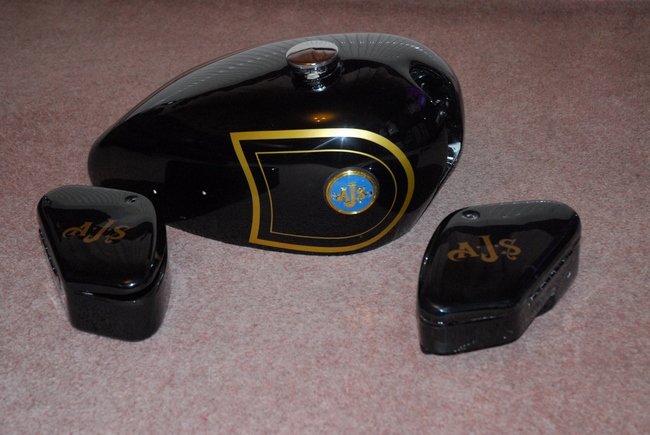 A brief update... First... I've got the petrol tank and tool boxes back from "Ernie the Paint" and very nice they look, too. The new tank badges look good and set off the gold pin-striping on the black tank. Gold "AJS" transfers now adorn the tool boxes. I'm not sure they were ever there on a new bike but I think they look the part, so they'll be staying. I've also got the speedometer back from Chronometrics. The trip register reset knob is now in the correct position and it's ready to be installed into the headlamp cowl. I'll need to put the headlamp on the bike first and complete the wiring connections but that shouldn't take long... famous last words!!
Progress has been made... The reconditioned 'short' dynamo arrived this morning. That's the last of the bits I've been waiting for. Today I finished the wiring and the new headlamp and sidelights are all working as they should. Unfortunately, rain stopped play so installing the dynamo and re-assembling the primary drive will have to wait a while longer. Ho hum...
 Didn't have to wait too long, fortunately. The weather today was kind to me so I was able to get two or three hours in. The new dynamo has been installed and connected up to the rest of the electrical system. That's the wiring totally finished, now. What's more... it all works. At least the lights and horn do. I'll have to wait until I get the engine running to check that the dynamo is doing its stuff.
With the dynamo on and the drive chain correctly adjusted, I could put the primary drive back together. As I said right at the beginning, the guys I bought it from had replaced the clutch. Well... they'd replaced the 5 friction plates anyway. Pity they didn't do a proper job and replace the plain plates and the springs at the same time. The plain plates were flat and not warped but they were very rusty. I spent half an hour or so cleaning all the rust off before I did anything else. I checked the length of the springs and they were on the bottom limit but still useable.  The clutch centre boss was first assembled onto the gearbox first motion shaft, that was followed by one of the thrust plates. The primary chain was wrapped around the clutch drum and the engine sprocket and the whole lot offered up to the clutch boss on the gearbox shaft. Then came the tedious job of putting back all 24 of the loose 1/4" rollers that make up the bearing. Fortunately, there were no problems and I hadn't managed to loose any of them. That done, the second thrust plate was put back followed by the centre drum. [EDIT... I should have been more observant here. All will be revealed later!!] I'd already bought a new nut and lock washer as the ones I took off had been badly mauled about. With that secure, it was just a case of putting back the plates, the pressure plate, the five springs and securing nuts. The clutch was then adjusted and set up correctly. The last thing was the shock absorber cam and spring on the crankshaft. They were slipped on and a new nut was spun into place with the air wrench that I'd used to remove the old one... Job done. The chain case outer cover was put back and that was it for today.
Another bright and sunny morning, so hopefully, I'll finish work on Bess today. The first job was to pour some oil into the top of the engine. That will drain down into the crankcase and prime the oil return pump. I poured in about a half pint of Halford's finest "Classic 20W-50" which should be enough to get the pump started. That done, the two tool boxes were bolted to the frame with new stainless screws and Nyloc nuts. The lids don't fit as perfectly as I'd like but they'll do. It's not as if I'm going to actually be carrying tools in them, after all. That just left the petrol tank and seat to fit. Four bolts for the tank and a couple of screws for the seat... Proper job!!
After a brief break for a cup of coffee, supplied by my neighbour, Wanda, the oil tank was filled and 5 litres of petrol poured into the fuel tank. Time to see if all the hard work, stress and not inconsiderable expense has been worth it. The little beauty fired up at the second attempt and settled down to a smooth(ish) tick-over. After a tense few moments waiting, the oil started returning to the tank. Yippeeee. The new dynamo is doing the business as the ammeter is showing a healthy charge with the headlight on. All seems to be working as it should. The high temperature sealant around the exhaust didn't immediately blow out so it looks like that might be successful, too. Happy days.... As somebody famous once said, "All a bloke needs is a bike to ride and a satellite to steer her by." Well... something like that, anyway!
Captain's Log - Stardate 20161206 [Supplemental]...I've put a few miles on the clock now and all seems to be well. There are no massive oil leaks and even the primary drive case seems to be pretty much leak free. Bess starts without problem and runs well. The engine oil is circulating as it should although it's not getting very warm. 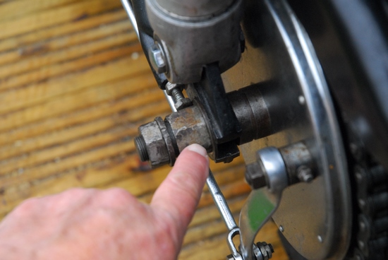 Probably due to the low ambient temperature and the fact that I'm only doing journeys of 20 miles or so. I did notice that the final drive chain needed adjusting the last time I went out so today I set about finding out how the back wheel adjustment works. Ho hum... the PO has struck again!! We have a totally wrong nut holding the 'dummy' axle in place. The bike has a 'Quickly Detachable' [QD] rear wheel. To remove the wheel, the nut on the main spindle is undone and the spindle removed from the right hand side. Once the spacer adjacent to the speedo drive has dropped out, the wheel can be pulled free of the brake drum and removed. The brake drum, final drive sprocket and chain remain in the rear forks, mounted on the 'dummy' axle.
To adjust the chain tension, both the nut on the spindle and the nut on the 'dummy' axle need to be slackened off and the whole assembly moved in the swinging arm by turning the adjusting screw, one on either side. Unfortunately, this is not possible at the moment as the incorrect nut on the 'dummy' axle prohibits the movement of the adjusting screws. This is further complicated because the PO has used totally inappropriate M6 screws instead of the correct 1/4" x 26 t.p.i. threaded adjusters. A complete new stainless axle assembly (with the correct nuts and adjusters) has been ordered and will be fitted in due course. 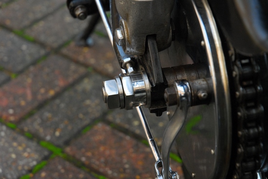
The new stainless bits have arrived and have been duly fitted. The bearing oil seal assembly on the speedometer drive side of the wheel has been stripped, cleaned and replaced with a new oil seal as the old one was well past it's 'best before' date. The wheel bearings are of the tapered roller variety and need to be set up with the correct 'free play' to ensure trouble free running. Easy enough, really. Tighten up the bearing adjuster ring until there is no free play, back it out 1/2 a turn and tighten up the locking ring. That should give the required 1/64" movement at the wheel rim... and unsurprisingly, it does!
Everything is now back together, the chain has been adjusted and I'm a happy bunny once again.
March, 2017. Bess has been out and about on a few rides so far and I'm happy to say that there are no unforeseen (or even foreseen) problems. She runs well, sounds lovely and is, quite honestly a joy to ride... With one proviso... The exhaust pipe fit into the cylinder head and the resultant crackling and backfiring on the over-run. The high temperature sealer that I had high hopes of failed to do the business. It didn't harden before the exhaust gas blew it all out. There is good news, however. Earlier this year I bought an abandoned Matchless G3 project from an elderly acquaintance. It had been dismantled some three decades earlier and had been stored ever since. Among the bits and pieces was a 500cc cylinder head from a 1960 AJS M18. It's grubby but mechanically it's in very good condition and most importantly, the exhaust port is perfect!! At some point later (this year?) I'll build it up with valves and swap it for the one currently on Bess... Job done!! [EDIT... Ha, Ha!!]
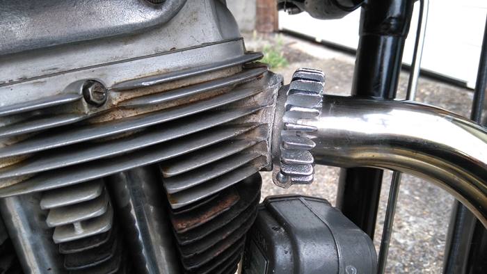 July, 2017. As mentioned previously, the exhaust port in the cylinder head of my '55 M18S has, over the years, become enlarged to the point where the exhaust pipe fits like a pound of sausages up the Blackwall Tunnel. A couple of days ago I tried something a little different in an attempt to cure the problem. I cleaned the head and the pipe and re-sealed the joint with 'Hylomar' exhaust paste. I used a propane torch to cure the exposed paste in the joint and then slid a Triumph exhaust pipe finned clamp up to butt against the head. I started the engine and left it ticking over for about 10 minutes. Everything seemed to be ok. The finned clamp held the paste in place while it cured completely. Took the bike out today for a 20 mile ride and that seems to have done the job. No air leaking into the exhaust and no annoying back-firing on the over-run but I was surprised by how much it had affected the carburation. The engine was definitely unhappy at small throttle openings. It was 'hunting' and made it awkward trickling through traffic. I stopped in a lay-by and had to back out the air screw on the Monobloc carburettor by a complete turn before it was running happily again. I'll still fit the replacement head in due course but for the moment the urgency has been reduced.
October, 2017. Whilst there's been a bit of a 'lull' in the progress on the G3/LS restoration, I've been thinking more about replacing the cylinder head on Bess. I had a telephone conversation a few weeks ago with Ken DeGroome, a well known and well respected AMC engine builder and the subject drifted around to valve timing. I asked him why the inlet valve timing was retarded by one tooth, that's 18°, compared to the 350cc engine when they both used the same cams and timing gears. His answer was that the 500cc was more likely to be used hauling a sidecar and AMC wanted the engine to be a bit of a 'slogger' so the inlet timing was retarded. An easy way to 'pep up' (Ken's words) the 500cc engine was to use the 350cc timing marks. You could also go one step further and use the inlet pushrod rocker arm from a later 'lightweight' 250/350cc engine which was about 1/8" shorter. That would effectively change the rocker ratio and give the inlet valve more lift. All that seemed like a good idea to me... well it would, wouldn't it! I already had the cylinder head from a later engine and I managed to source a pair of lightweight rocker arms from another AMOC member.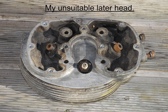
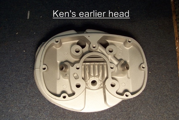 That's when I discovered that I had a problem... Talking to Ken about my intended mods, I learned that the replacement cylinder head I had was not suitable for my engine. It was for the later 'short stroke' engine. The head would fit but the compression ration would be significantly reduced and as it's not exactly high to start with, any reduction was definitely not a good idea. Fortunately there was a "however...". It transpired that Ken had been looking for a later cylinder head for one of his projects and he also had a head that would be suitable for my engine. We agreed that a straight swap would be beneficial to both parties so I'm now in possession of an excellent, vapour blasted earlier head and Ken has my somewhat grubby later one. Reckon I got the best of that deal!!
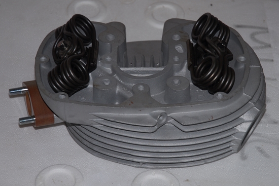 Friday, 23rd February, 2018. While the weather has precluded me from doing any serious work on the G3/LS project I've not been totally idle. I've replaced the valve guides in the replacement head, re-cut the valve seats and lapped in a pair of new valves. The new valves threw me a bit as I'd ordered a new pair from Steve Surby at AMC Classic Spares and was expecting a new inlet and a new exhaust valve. I received a pair of exhaust valves! A quick phone call resolved the issue... On the 500cc engine, the inlet and exhaust valves are exactly the same size (which explains Ken DeGroome's comment to me that the engine is "over exhausted"). The difference being that the exhaust valve was originally made from a better grade of steel to cope with the higher temperature. Rather than keep the same valve in two different materials, these days only the better grade of steel is used and the same valve is fitted to both the inlet and exhaust.
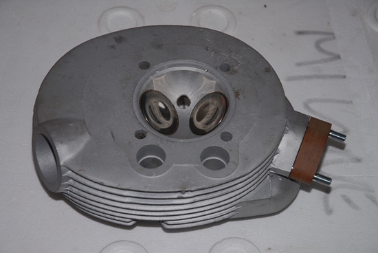 I wanted to build up the head completely so that it could be swapped with the minimum of 'messing about'. Looking thorough my stock of bits, I had a pair of valve spring seats and one collet retainer. I needed another collet retainer, a set of collets and a set of valve springs. The collets were not a problem as Andrew Engineering had them is stock. A quick check on eBay and another used, original collet retainer was soon on it's way to me. New hairpin valve springs are available, for a price, but both Steve Surby and Ken DeGroome advised me not to use them as apparently they were much inferior to the original springs. A few days later, a set appeared for auction on eBay. They were original, early 60's items and looked to be in excellent condition. I won the auction a few days later and today they arrived. I now had all the necessary bits so it was the work of just a few minutes to re-assemble the cylinder head. The valve stems were given a coating of 'Graphogen' colloidal graphite paste to protect them on initial start-up. Job done... I'm not sure exactly when I'll get around to swapping the heads but hopefully it won't be too long before the task is completed. It's never too late to learn something new, and I have learned something about valve springs. Those of you that have been paying attention will have noticed a discrepancy between the valve springs I've just fitted to the new head and the valve springs fitted to the old head, pictured near the start of this saga. The old ones have four full coils on each side, while the ones I've fitted to the new head only have three. [Start of lesson] The 250cc and 350cc lightweight engines have valve springs with 3 coils each side but are made from the same gauge wires as the heavyweight springs, which have 4 coils. The later short stroke engines revved higher and it was decided that stronger springs were needed. These later springs only have three coils but are made from a thicker gauge of wire, and are therefore stronger. These are the ones fitted to Bess. [Here endeth the lesson].
Thursday, 26th April, 2018. Today I brought Bess up from the garage so that I could finally get the head changed. In very short order, the exhaust pipe was removed, the rocker box and head were off, the magneto drive dismantled and the timing gears removed. So much for taking it apart. The only problem I found was on the inlet pushrod. The bottom steel ball end was loose on the aluminium tube. It was cleaned, roughed up slightly and put back together with a little "Loctite 638" high strength retainer specifically designed for bonding cylindrical parts. That will sort out that little problem.
Some time ago, I had cause to post a photograph of the bikes 'top end' on the AMOC forum. One eagle eyed contributor spotted the part number stamped into the mounting flange of the Amal Monobloc carburettor that was fitted and informed me that it was not the correct model for my bike. No surprise there, then, given all the other problems that the previous owner had given me. A quick check on the AMAL website confirmed that it was indeed incorrect. Not only was it too small, a 376 series 1.1/16" bore instrument instead of the correct larger 389 series Monobloc with a 1.5/32" bore but it was originally fitted to 500cc and 600cc Norton twin cylinder machines from the early '60s. As the whole object of this exercise is to increase the performance a bit, there's not a lot of point in having a carburettor that is too small. As I needed a few other small bits and pieces to complete the task, a quick trip up to the AMOC Spares counter in Kettering was called for. With a new carburettor, a couple of gaskets and a pair of stainless pushrod tubes safely stashed in the back of the car, I headed home to complete the job....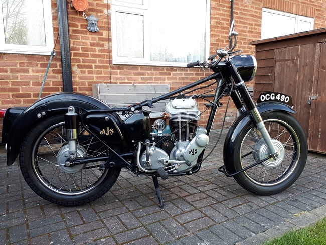 Bummer... rain has stopped play so I'll have to wait for the better weather that is forecast for next week. I did work in the shed for a short time cleaning up the parts I'd removed and to swap the inlet pushrod rocker arm for the slightly shorter 'lightweight' arm that I'd acquired some time ago. That will change the rocker ratio and give the inlet valve a little more lift.
Tuesday, 1st May, 2018. Today was a good day. The weather has taken a very definite turn for the better and it was warm and sunny. Time to get cracking with the modifications I've planned for Bess. First job today was to drain the oil from the engine, gearbox and primary chain case. With that done, the primary chain case outer cover was removed. The chain was just a little slack so the gearbox was shifted back a touch to get the tension right. The dynamo chain was also adjusted as that too was a little loose. The camshafts that I'd removed earlier were but back only now they are on the advanced timing, same as the 350. With the cams back in place, I could retime the magneto. The book says 1/2" B.T.D.C. but the general consensus is that retarding it a bit to 7/16" is better with the modern petrol to avoid 'pinking' so that's where I've set it. The top end was reassembled with the 'new' head and that's about as far as I've got today.
Friday, 4th May, 2018. Some days are very definitely better than others. Yesterday started off well. The last few little job like mounting the new carburettor and fitting the cables went without too much trouble. I did have to modify the throttle cable a little but I expected that. From my experience, cables seldom fit perfectly straight out of the box. That done, the tank was put back, the fuel lines connected and the seat re-fitted. A quick check that I'd put oil in all the right places and nothing was loose so I dumped 10 litres of petrol into the tank. I flooded the carb, gave her a couple of kicks and away she went.... 'Kin 'ell... where's all that smoke coming from? I literally couldn't see across the yard it was so thick. I wasn't expecting that! I stopped the engine and had a think. 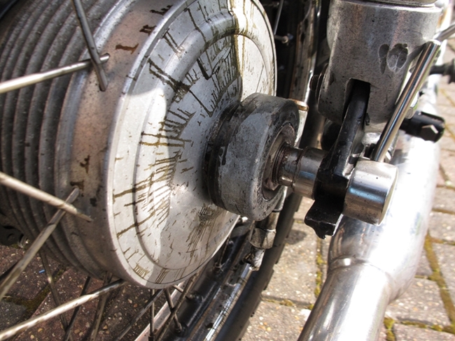 Then it clicked... The bike had been standing all winter. I'd drained the oil tank, gearbox and primary chain case but I hadn't drained the crankcase. Over the winter half the oil in the tank had drained back into the engine. I pulled the sump plug and drained out a couple of pints of old oil. Ho hum... I should have known by now that these things 'wet sump' if left for any length of time. With the engine now running cleanly, it was time to take her out, get her warmed up and tune the carburettor. A quick run to Hitchin and I stopped to give the air screw and throttle stop screw a little tweak and she was ticking over cleanly so I carried on through the lanes to the Two Wheel Centre for a cup of tea. Everything seemed to be fine... until about halfway home when the speedometer drive gearbox on the rear wheel locked up and spun with the wheel, destroying itself and the cable in the process. That brings us up to this morning...
I took out the rear wheel to inspect the damage. The speedo drive was bent and distorted enough to make removing the retaining nut impossible so that was cut off with the angle grinder. There was some serious damage to the threaded drive spacer so I made a list of the parts I needed to replace. Fortunately, they were all available from AMC Classic Spares and that very nice Steven Surby said that he was going to be there all afternoon so I could go over and collect them if I wanted... I did. One last thing for today... The new exhaust pipe and silencer arrived so that was fitted. Tomorrow, I'll rebuild the back wheel with the new bits and hopefully, Bess will be back on the road again!
Monday, 7th May, 2018. The rear wheel speedo drive assembly was re-assembled on Saturday and it all went back together without any drama. A 60 mile ride out confirmed that all seemed ok. Sunday morning a longer ride down to Ryka's Cafe on the A24 at the bottom of Box Hill also proved uneventful. Brought the bike up from the garage this morning for quick a check to see that everything was as it should be. It wasn't... The wiring underneath the rear mudguard had not been put back in it's retaining clips and had been rubbing on the rear tyre. That's my fault entirely. I should have checked when I put the rear wheel back in on Saturday. No big deal... Just needed to replace a short section of the wiring harness. I needed to readjust the primary chain a little and the inlet valve clearance had opened up a little so that was also reset. Have to keep an eye on that as it was the inlet pushrod that had the loose end. One thing I did notice was that the engine was sounding quite err... 'busy' when running at 70mph. The gear ratios seem to be quite low and pulling away in second gear is not difficult. It may be time to think about a larger gearbox sprocket to raise the gearing a little.
Tuesday, 15th May, 2017. Having checked the sprocket sizes on Bess, I've discovered that a previous owner (may the fleas of a thousand camels infest his arse hole!) had installed the wrong sprockets. Bess has an 18 tooth engine sprocket fitted, which would be correct for the 350cc Model 16, where she should have a 21 tooth sprocket. That has the effect of lowering the overall gearing from the standard 5.00:1 to 5.833:1 That's a 16% lowering of the gearing! When I bought the bike, the dealer had replaced the final drive chain and sprockets. Fortunately, they had put on a 17 tooth gearbox sprocket instead of the the standard 16 tooth sprocket. That raised the gearing back up a little to 5.49:1 but the bike is still under-geared by 10%. No wonder she was sounding 'busy' at 70mph. I've managed to locate a usable 21 tooth engine sprocket and will in due course, swap it for the 18 tooth item. I'll leave the 17 tooth sprocket on. That will give me an overall top gear ratio of 4.7:1 which will be much better. I have to strip off the primary drive anyway because the idiot who 'restored' the bike before I bought it has put the swinging arm pivot end plates on the wrong way round. This means that it's impossible to refill the oil reservoir as the filler plug is hidden behind the primary chain case. I have new end plates and gaskets so I'll correct that mistake when I swap the sprockets. Ho hum....
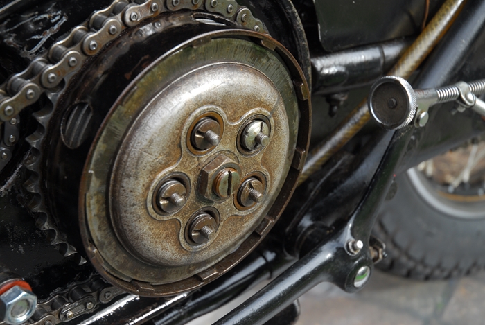 Friday, 1st June, 2018. Ho hum indeed... PO strikes again. Today I started to take the primary drive off to enable me to change the swinging arm pivot end plates. Once I'd drained the oil and removed the outer cover, something caught my eye. It was the Burman clutch assembly; the five studs that secure the springs were sticking way too far through the nuts. The end of the studs, the nut's outer face and the pressure plate should all be roughly level. [This is something that I should have noticed when I had the engine out to fix the oil pump problem back in September 2016. I'm going to put my 'oversight' down to not being familiar with the bike at that time as I'd only had it a little while.] Also, the last clutch plate was a long way down inside the outer clutch drum. I started to wonder if I'd got the wrong number of plates installed. I unscrewed the five nuts and removed the pressure plate. The last steel plate was just about flush with the outer edge of the clutch hub... there was no room to fit any more plates. I removed all the clutch plates... five steel plates and four friction plates. There was a pair missing!! The 500cc M18 should have six steel plates and five friction plates but the clutch hub was too short. The bloody PO had installed a shorter clutch hub from a 350cc M16 and used one less pair of plates. Time to look for longer 500cc clutch hub and source another pair of plates.
I carried on and stripped off the rest of the primary drive and the dynamo drive before removing the inner half of the chain case. I will have to get a new primary chain as the one I took off was too short to accommodate the larger 21 tooth engine sprocket that I will be fitting in place of the 18 tooth sprocket the PO fitted. It was quite worn anyway so not a bad thing to replace it.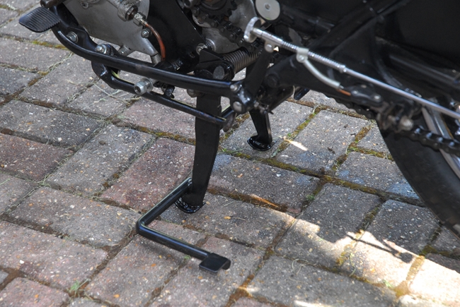 With the primary drive out of the way, it was a relatively simple matter to remove the swinging arm pivot end plates and install the new ones, the correct way round.
Saturday, 2nd June, 2018. A couple of months or so ago, one of the AJS & Matchless Owners Club Members, Rob Swift, was developing a 'revised' centre stand for the bikes. It incorporated a foot operated lever, similar to the one on the Triumphs of the period, that made getting the bike onto the stand something of a 'doddle'. It was tested, proved successful and a small 'production run' was made. I was lucky enough to obtain one and today, as I'd already got the primary drive stripped of, I decided to fit it. It wasn't the easiest of tasks but I prevailed and I now have it installed. It really does make getting the bike on the stand easy. Rob claims he can do it in his socks but I'm not about to test that claim.
Saturday, 9th June, 2018. Once again, it's one step forward and two steps back. I'd collected together the parts I needed to rebuild the clutch in the correct 500cc configuration and this morning I started on that. 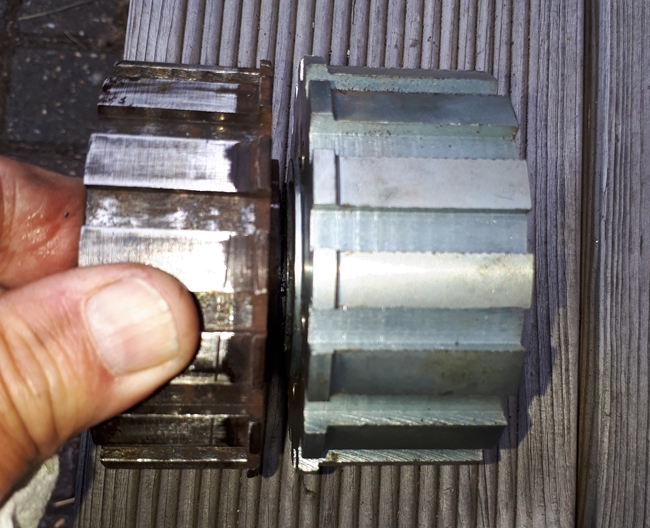 The primary drive was re-installed with the correct 21 tooth sprocket and the new primary chain. The new longer clutch centre hub was secured to the gearbox mainshaft and the clutch plates, with a new pair added, were slid into place. It was only after I'd fitted the pressure plate that I found the first 'snag'. The adjusting screw in the pressure plate seemed to be going in too far before it contacted the end of the clutch pushrod. There was not enough thread left exposed for the lock nut. I've measured the pushrod and at 10.3/16" long, it's the correct length for a 5 plate clutch so that is OK. I wondered if the 5/16" diameter steel ball that the pushrod bears on at the gearbox end had been omitted to effectively shorten pushrod as the clutch had be built up with one pair of plates less than there should have been. I "Araldited" a small neodymium magnet into the end of a length of 1/4" copper tube and poked it into gearbox mainshaft. It seems I used the right bait as I fished out the steel ball... so that's not the problem either. The clutch plates are all correct so that only leaves the adjusting screw itself. It doesn't look quite right and I think it may have been modified by drilling a hole into it so I've ordered a new correct one from AMOC Spares. We'll come back to this in due course.
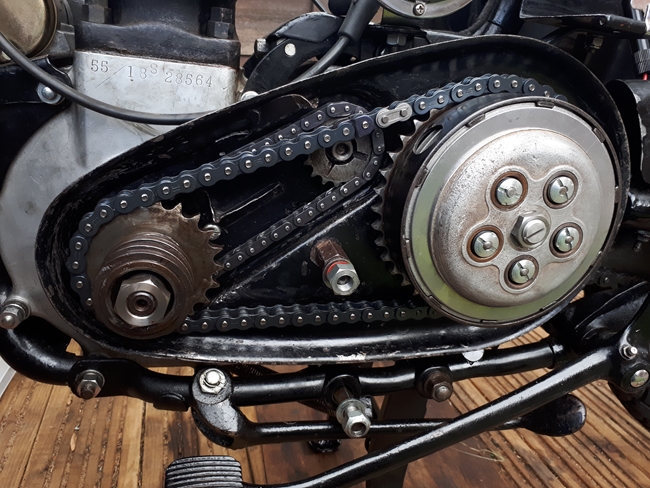 [3 days later... Problem sorted with a new adjusting screw, a slightly modified centre hub (it needed the inboard flange machining to the correct thickness.) and a slightly longer clutch push rod. That was made from a length of 5/16" 'silver steel', hardened at the ends.]
Sunday, 10th June, 2018. I'd noticed, after the last ride out, that the engine seemed to be 'rattling' a bit louder than I thought it should be so while I waiting for the clutch adjusting nut, I whipped off the tank and seat so that I could remove the tappet cover and check the valve clearance. I put a spanner on the engine sprocket nut and turned the engine over to T.D.C on the compression stroke. The valve clearances were fine, the pushrods were free to rotate but the was no "up and down" movement detected... just as they should be. Then it dawned on me... I'd just turned the engine over compression with a shortish spanner and there wasn't any... compression, I mean. As I turned the engine over compression, there was just a hissing of escaping gas back through the carburettor!! It was very definitely one of those "Oh, f**k it" moments. As I'd changed the inlet valve timing and increased the inlet valve lift, I thought I'd probably 'over-done' it and the valve had hit the piston and bent the valve stem. Half an hour later, the cylinder head was on the bench. The inlet valve looked to be seating ok and wasn't obviously bent... I pulled the valve springs off and dropped out the inlet valve... and the inlet valve seat dropped out as well. That wasn't supposed to happen but it explained the lack of compression, the compressed gas was escaping back through the carburettor between the valve seat and the cylinder head. Maybe the head I'd got from Ken DeGroome wasn't such a great deal after all. Anyway...
Monday, 11th June, 2018. After the SGS Inspector had been to have a look at Alice for the DVLA, I took the cylinder head over to T & L Engineering for their assessment. Not a problem, apparently. They can sort it out and fit a new inlet valve seat. They will put in a hardened exhaust valve seat at the same time. That will make it OK for regular pump petrol without having to put any lead additives in. I've asked them to take a skim off the head joint face while they had it as I'd noticed there was evidence of it 'blowing' at the front just a little. The saga continues...
Friday, 3rd August, 2018.
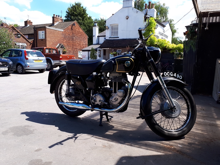 I collected the head from T & L Engineering on Tuesday. They have done the expected fine job. The exhaust valve seat has been machined out and a new hardened steel one fitted. That will alleviate the need for lead replacement additive and she will run on pump un-leaded petrol now. The loose inlet valve seat has been removed and the head welded up. It has been re-machined and a new valve seat insert installed. Both seats have been re-ground and the valves lapped in. The head joint face and spigot recess have been skimmed a few thou as there was evidence of the head joint 'blowing'.
Yesterday, I put the whole shooting match back together. She was a little reluctant to start but we got there in the end. A short run out to the Strathmore Arms confirmed that Bess was indeed back to her former stroppy self. Today we went for a longer run. A cross country ride to the Angler's Retreat at Marsworth and back home again through Ashridge Park. She is running very well. The uprated clutch is smooth and has a light action. The 21 tooth engine sprocket to raise the gearing has made all the difference. No longer does she sound as busy as she did and 70mph is comfortable. All in all, I'm well pleased with one exception. She is still very noisy mechanically. I don't think it is anything as low down as the crankshaft or the big end, at least I hope it isn't. It could be that the the camshafts are moving with too much end float. Shim washers are available in different thicknesses to get that correct. That's something to check at some point in the future. She ran well enough yesterday, easily pulling 70mph on the A505 dual carriageway and maintaining that speed over the top of Offley hill. However, for the moment at least, all bike work will have take second place to me moving home. When I've settled in and got a workshop sorted, maybe Bess will get a complete rebuild like the other three bikes in my 'stable'.
The saga continues... See "Part 2" by clicking HERE.
Link to Index and Home Page.
Link to Matchless G3/LS page.
Link to Triumph Tiger 90 page.
Link to Triumph Bonneville T120R page.
Link to Matchless G80CS page.
Link to Honda VFR750 page.
Link to Norton 650SS page.
Last updated 24/10/2021