Tuesday, 24th January, 2023.
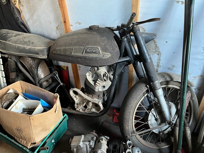 This came out of the blue, totally unexpectedly. My friend, Clive, sent me a "WhatsApp" message and some photographs of two old British bikes that his brother-in-law, Ted, owned. They were his last two; the other bikes that he owned had already gone to auction. They were a 500cc Velocette "Café Racer" that Ted had owned since his youth, and a Norton Dominator 650SS that hasn't seen a road in decades. The message that accompanied the photos asked me if I was interested in buying them. The Velocette looked to be pretty much complete, but the Norton was very definitely not. At least, it was in bits, and it was obvious that both needed an awful lot of work to make them road worthy. I'm always up for a challenge so Clive took me to meet Ted and his wife, Cheryl, to have a look at what was on offer. To cut the story a little shorter, the Velocette needed just too much work and expense to bring it back to the way it was originally. As a Café Racer, it wouldn't command the resale price that would come anywhere near to the cost of restoring it. So I passed on that one. Ted and I haggled a bit but in the end, I agreed to buy the Dominator and the boxes of bits that supposedly held the associated parts. Hope I've made a sensible deal. Time will tell! Clive has a towing hitch on the back of his Land Rover and with a large trailer borrowed from another friend, Jean-Pierre, we intend to collect the bits from Ted on Sunday, 12th Feb. I have a number of other projects to complete before I can start work on this one so it will be a while before anything is added to this web page.
Sunday, 12th February, 2023.
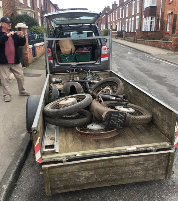
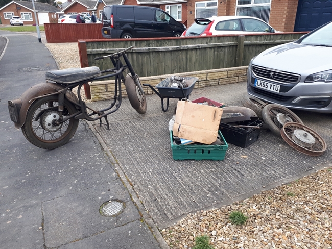 This morning, Clive picked me and Jonny up in his Land Rover. We collected the trailer from Jean-Pierre and headed north to Horncastle. Cheryl had put cones out to reserve a parking space for us, fortunately, as the road was narrow and full of parked cars. We loaded the trailer with all the stuff that Ted wanted to get rid of. It's not all Norton stuff... There is at least one wheel that is definitely AJS / Matchless. There are two AMC gearboxes, which I suspect were original fitment on a Norton as the top mounting boss is slightly narrower than the AMC gearboxes fitted to the AJS / Matchless bike. I'll know better when I've cleaned them up a bit as they are very grubby. I've put all the stuff in Shed Ten for the moment. I'll sort through what I've got in due course and formulate some sort of action plan.
Saturday, 25th February, 2023.
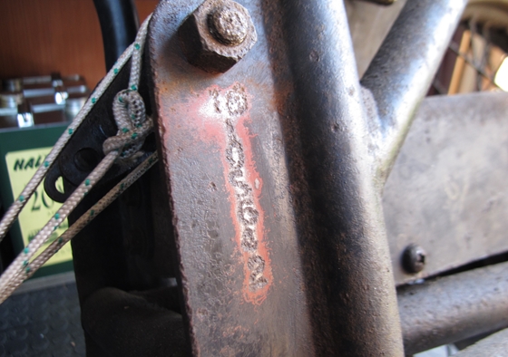
While I had a few hours to spare, I thought I'd have a look at one of the two AMC gearboxes. I picked the grubbiest one because that was the one with the number "N 10485" stamped into the top of the case. I'm hoping that it's the original gearbox for the bike. The second gearbox was a lot cleaner (on the outside) but has no number on it that I could find, so I think that it maybe one that Ted had acquired from somewhere else at some time.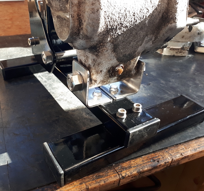 The first thing I found was that it didn't fit the work-stand that I'd made for the AMC gearboxes that are fitted to my Matchless/AJS machines. The mounting bosses were much further apart. That meant that I had to modify the stand by adding a pair of small angle brackets to secure the bottom mounting. No big deal in the great scheme of things but it did delay me somewhat.
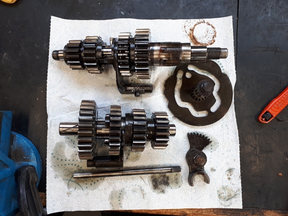
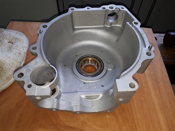
Surprisingly, the gearbox came apart relatively easily. It had obviously been apart before as there were one or two small 'dings' in the joint faces, but nothing to be overly concerned about. The nut securing the mainshaft into the bearing in the inner cover took a bit of shifting. In the end, I resorted to using the gas torch to get it sizzling hot then hit it with the big air impact wrench... That did the trick!! I suspect that it had been assembled with some sort of Loctite adhesive. With that nut out of the way, the inner cover came off with a few light taps with a soft faced hammer. Everything else was disassembled easily. All the internals looked to be in very good condition. There was no play in any of the bronze bushes or their respective shafts. The selector cam plate and selector arms were good. The output sleeve bearing and oil seal were removed, as was the mainshaft bearing in the inner cover. The ball bearing for the layshaft is set into a blind hole in the case and wouldn't move using the slide hammer, so the case went into the oven at 180°C for half an hour. A light tap onto a wooden block and the bearing dropped out. The case, inner and outer cover were washed in the parts washer and dried off. I'll get those aqua-blasted at some point before reassembly.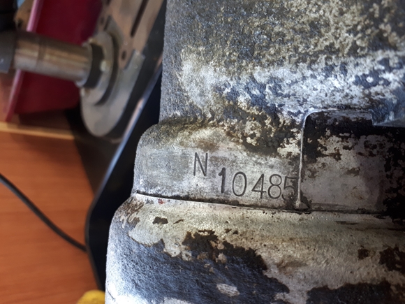
Wednesday, 1st March, 2023.
Yesterday, I took the gearbox casings to Simon at Bike-Aquablasting. He very kindly did a quick turnaround job on them for me while I was enjoying a pint of lunch with mates Rob & Les at the George & Dragon in Stoke Golding (highly recommended if you're ever that way). As usual, he's done a great job.
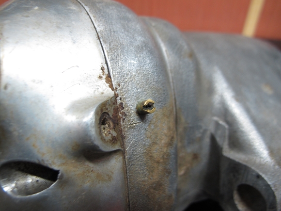
I've also learned something about the two gearboxes I have. The one I've taken apart has a number, prefixed with the letter "N". This tells me that this gearbox was manufactured prior to 1963. From 1963 onward, the prefix changed to "NA". As the bike's number indicates that it was probably built in early 1963, it's quite likely that the gearbox was built in 1962, before the "A" was added to the number prefix. The other gearbox that I have has a tiny "breather jet" fitted to the inner cover, adjacent to the cable entry. This was to improve the gearbox breathing, but this modification wasn't introduced until 1975, when the Mk 3 Norton Commando was launched. Potentially, that is both good and bad news. The good news is that this gearbox has a number of improvements over the earlier versions, but it doesn't have a number stamped on it. In the great scheme of things, that may or may not matter. I will, in due course, take this gearbox apart. It may be that I can just swap the cases, thereby keeping the number but with the added benefits of the upgraded internals. If not, then I may just use the later gearbox anyway.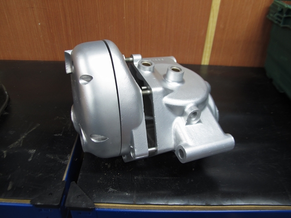
Tuesday, 7th March, 2023.
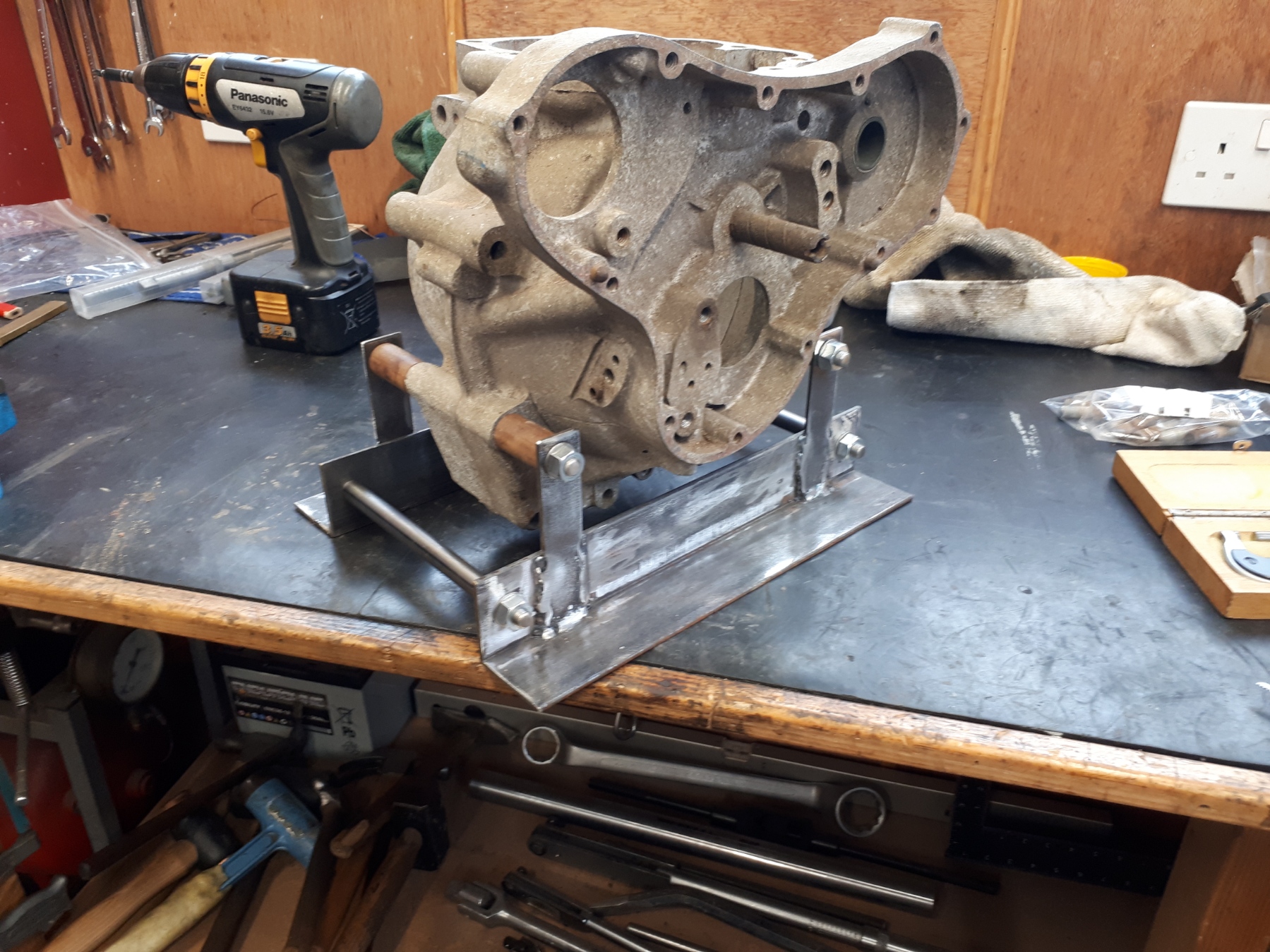 I have not been idle the last few days. The Norton engine won't fit into any of the engine support stands that I have which isn't really surprising as they are for Triumph twins and AMC single cylinder machines. You can't work on an engine with it rolling about on the bench so I've knocked up a simple stand from some angle iron and steel strip. It's not elegant but it does the job admirably. I'll get it powder coated black in due course.
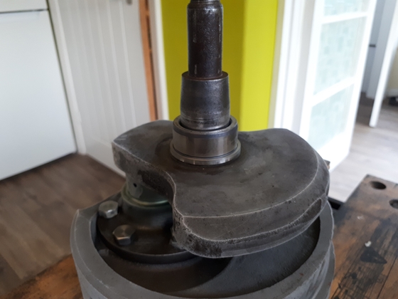
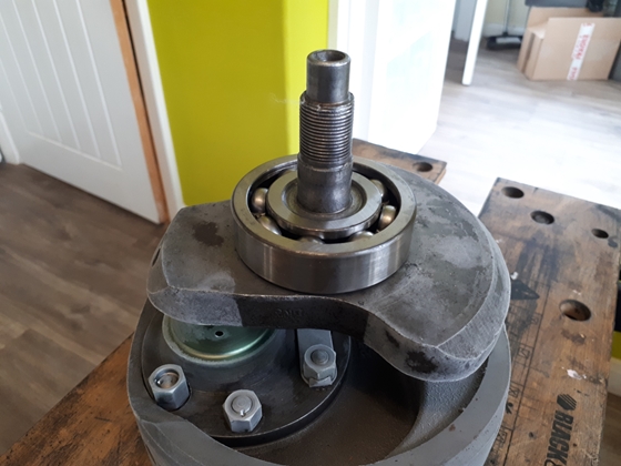
If I'm to use the original, matching numbers, crankcase then I need to know that it's in good enough condition. I thought I might be in trouble with all the old rusty steel parts that had been left on the crankcase. I was pleasantly surprised when all the rusty steel studs gave up without much of a fight. Even the timing chest idler pinion spindle tapped out easily once I'd had that half of the crankcase in the oven for half an hour. That only left the drive side main bearing outer ring. I put that half of the case in the oven at my normal temperature of 180°C for 30 minutes than dropped it onto a wooden block. That usually works but this time it didn't, the ring stayed stubbornly put. I really did not want to think about splitting the ring with a die grinder so I upped the temperature to around 210°C. That was as hot as I dared take the case. This time, there was a satisfying 'ting' as the ring dropped free. Result. Now I'll get the cases vapour blasted. That way I can assess them properly.
I've also dismantled the second gearbox. It is indeed a later version with the uprated internals. If I choose to combine the two boxes, I'll use the numbered case from the older box with most of the original internals. I will swap the two 2nd gear pinions as they are stronger and I will have to use the inner and outer covers from the newer gearbox if I'm to use the better kickstart shaft and spring. When the time comes, I'll put everything together 'dry', to make sure it all fits before reassembling it with sealer and gaskets.
Thursday, 9th March, 2023.
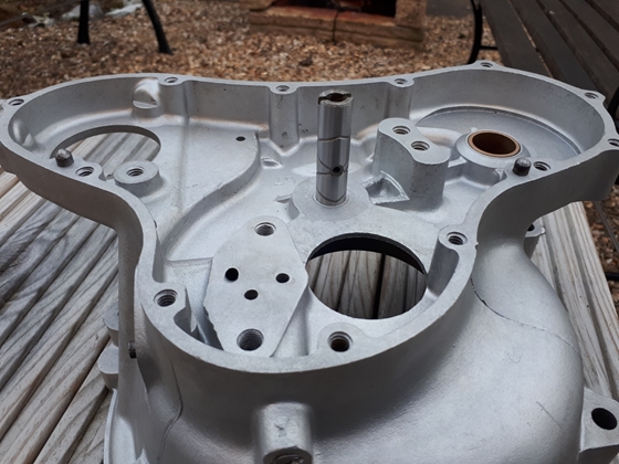
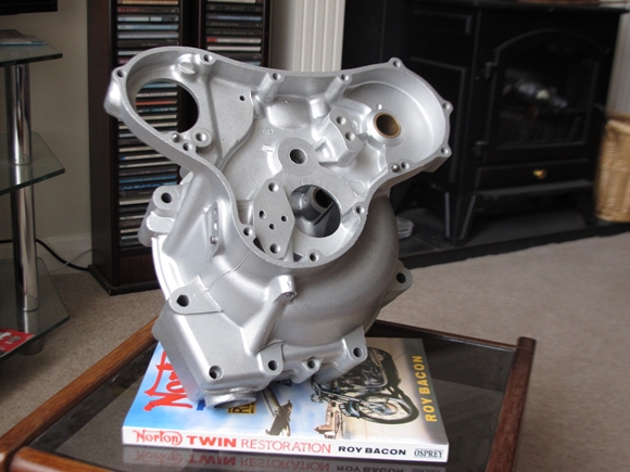 Yesterday, called into T & L Engineering in Elstow, with the matching numbers crankcase for vapour blasting. When Barry, the very nice gentleman behind the counter, found out that I was on my way back to Lincolnshire, he persuaded one of his guys to vapour blast it while I had a coffee in a 'foody' pub at the other end of the village. Half an hour later, the case was back in the car boot, fully cleaned. That is service above and beyond the norm, and saved me another 150 mile round trip to collect it at a later date. Thank you, Barry and all T & L Engineering.
Today, I had a good look at the cleaned cases. They look to be in excellent condition, fortunately. I don't believe that I'll have any problem using them, so today, I ordered some new studs to replace all the extremely rusty ones that I removed. I've also ordered a new intermediate pinion spindle as the one I removed was totally unserviceable. The only things I'm unsure about are the camshaft bearing bushes. I'll have to wait until I can offer up a camshaft to assess the wear, if any. At worst, they'll have to be replaced, but potentially, that's not too difficult.
Friday, 10th March, 2023.
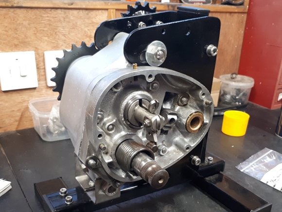
 Today, I've started to reassemble the gearbox that I'll be using with the bike. Basically, I'm using the numbered case and most of the internals that the case contained. I will, however, be using the kickstart shaft and ratchet from the un-numbered case as this uses the upgraded and stronger shaft and return spring. This means that I'll also have to use the inner and outer covers from the un-numbered box. Theoretically, it should all go together without problems. Whether or not that is true remains to be seen!!
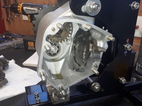
So far, I've replaced the three ball bearings and the output sleeve oil seal. That required that the case and inner cover be heated in the oven. I've put the selector plate and quadrant back in with new "X ring" seals to replace the old "O rings". It took me two attempts to get it indexed correctly but it wasn't really a problem. I've also fitted the output sleeve gear, a new 21 tooth sprocket, a new locking washer and new locking washer screw.
Sunday, 12th March, 2023.
 The gearbox is now mostly complete. The internals went back much easier than I expected, having had difficulty putting the Bonneville gearbox back together which has a similar vertically mounted selector cam plate. The only slight difficulty was getting the layshaft back into the the ball bearing at the back of the case. It took a couple of 'taps' with a plastic faced dead-blow mallet to persuade it that it really did fit!! As mentioned above, I've fitted the inner cover and kickstart shaft from the later gearbox and that went together without a hitch. The only reason the box isn't finished is that I found that I needed a couple of new nuts, which I didn't have. That was an oversight on my part when I ordered the bits. They've been ordered and I'll complete the gearbox when they arrive. I had to clamp the stand down to the bench in order to apply the 70 lb-ft of torque required to do up the mainshaft nut. That also had a little blue Loctite applied for added security. You do not want that nut to come undone out on the road... go on, ask me how I know!!!
Saturday, 18th March, 2023.
The nuts that I needed arrived during the week and today, the gearbox rebuild was completed. The gearbox was filled with EP80w-90 GL4 gear oil and put away in Shed Ten until required.
Tuesday, 21st March, 2023.
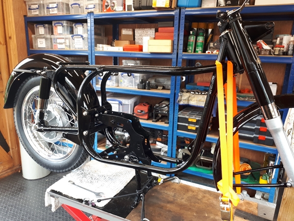
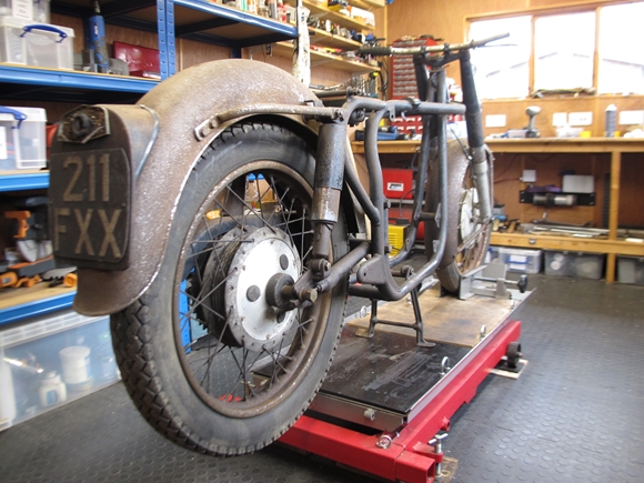 As Christine's tricycle project is almost complete and currently away for painting, the Norton rolling chassis has been brought into the workshop. I'm not going to do a lot with it at the moment. I know that there are a lot of bits missing. Hopefully, I can obtain or acquire those in due course. I'll put together what bits I have and so determine what is missing. I know the first thing I need to get is a set of engine plates. Once I've found them, I can put the engine and gearbox into the frame.
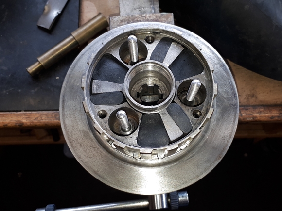
Having finished a gearbox, it seemed sensible to have a look at the AMC clutch that was in one of the boxes of bits. Hmmm... It seemed to be more or less complete but would need a little work. The cush rubbers were soft and manky and would definitely need replacing. That's straightforward but not totally without problems. I'd replaced them in the clutch on my Matchless G3/LS so I knew what I was letting myself in for. The hub was completely dismantled, the spider and old rubbers removed, then the whole lot had a session in the parts washer. How I replaced the rubbers, I've already related in the G3's web pages, and I used the same method for this hub. You can check that out HERE, if you're interested. With new rubbers in place, the hub was re-built with new spring studs and nuts. The cover plate was refitted with new screws. I was missing a pair of plates, and those I had were past their best, so it makes sense to replace them all... Four friction and five plain plates. I'll order new ones in due course.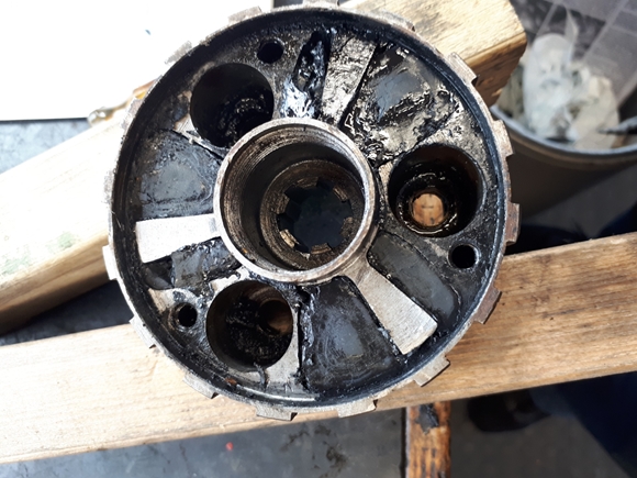
Saturday, 25th March, 2023.
Things are progressing nicely. The rolling chassis is now in the workshop and on the bench. I needed a set of engine plates as the ones that came with the bike were as much use to me as the proverbial chocolate tea-pot. They were for a Norton single cylinder engine and didn't fit the twin's crankcase. Andover Norton were able to supply me with a new full set of 4 plates. RGM Norton had supplied the stainless steel mounting hardware so it seemed rude not to put the lot together in the frame to see if every thing goes together correctly.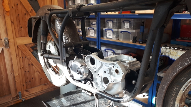 I'm happy to say that it does. However... (there's always a "however"), they didn't go together without a fight. A lot of the problem was my lack of experience with Norton machines. There is very definitely an order in which to do things and I didn't know that order. I found, by trial and error, that the rear engine plates have to be attached to the crankcase first, and that assembly offered up into the frame. That's when the first problem showed up. The 5/16" diameter stud in the bottom of the crankcase was too long and wouldn't drop down between the lower frame tubes. That had to come out and I removed a couple of millimetres off each end in the lathe. With that done and the crankcase / rear engine plates in place, the front engine plates can be wriggled into position and the mounting studs pushed through. That's when the next problem reared its ugly head. At some point in the past, one of the front lugs on the frame had received a knock and was bent just enough to stop the stud going through. The whole lot had to come out again and the lug straightened. That just left the gearbox. Fortunately, that could be positioned between the rear plates without any difficulty. So far, so good.
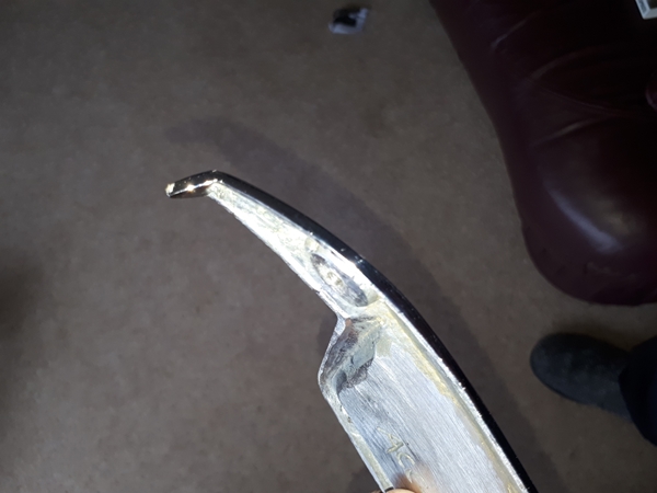
 I had a root around in the boxes of bits and found that I had the complete footrest assembly. I spent some time cleaning the muck and rust off and assembled them into the rear engine plates between the engine and gearbox. The chrome plated dome nut on the left hand side will need replacing as it is very rusty. With the footrests assembled, I could see that both were bent. If I was going to straighten them, now was the time, so the oxy-acetylene was fired up and with the wrought steel glowing bright red, the straightening torque was applied with an old fork stanchion. Much better!!
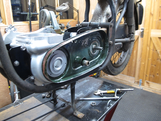
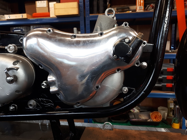
Last job today was the primary chaincase. I had one with the bike but I wasn't sure if it would fit. Having cleaned it and offered it up, I can tell you that it didn't. It's painted green, as were the engine plates that didn't fit, so I suspect it came from the same single cylinder donor bike. The inner chaincase fits, but the hole for the alternator cable is in the wrong place. That's an easy fix. I'll drill a new hole in the correct place and put a blanking grommet in the existing hole. The outer cover is a little more involved, I will have to carefully mark and cut the large outer flange to reduce its width. A job for the angle grinder with a cutting disc. Ho hum....
Sunday, 26th March, 2023.
Today, the primary chaincase outer cover has been trimmed down to the correct size for the twin cylinder engine. I had to remove a strip about an inch wide along about half of the perimeter. It was smoothed and de-burred on the grinder flap wheel, then offered up to the inner cover on the bike. It fits perfectly... splendid!. I'll probably prepare and spray the inner cover myself but the outer cover, I'll leave to the professionals. Kristian Vere at the local Lutton Body Shop made a splendid job of my damaged Triumph Bonneville rear mudguard, so I'll entrust the outer cover to them. If they do an acceptable job, I'll let them do the other parts that will, in time, need to be painted. There is just one more job to do on the chaincase cover. I need to cut a hole in the dome that goes over the clutch in order to adjust the clutch. The later covers had this hole in as standard and a plug is available to fit the hole.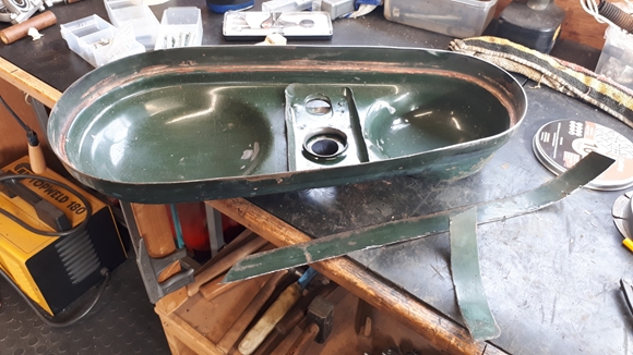
Tuesday, 28th March, 2023.
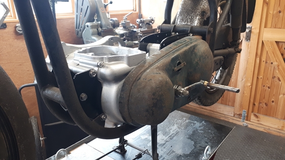
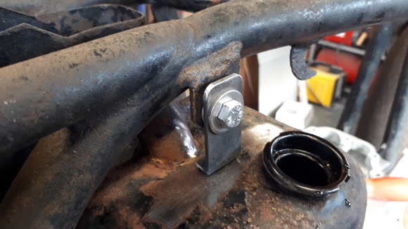
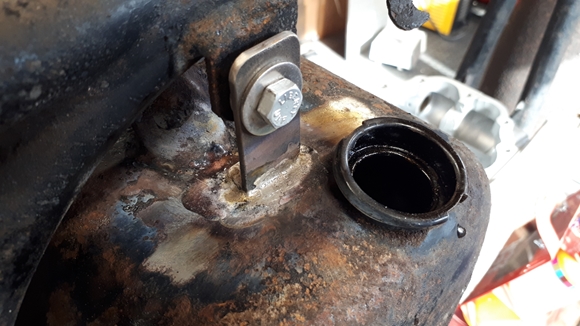
Having come this far, I thought it would be a good idea to bolt on any other bits that I had. This would give me some indication of what bits were missing and would need to be sourced. I had an oil tank, toolbox and the mounting plate for both that bolts across the engine plates. The mounting plate fitted with very little "adjustment", as did the two parts of the tool box / battery carrier. I'll need to see if I can get the lid to fit a little better but that's a minor thing. The lid will need a pair of new screws but they are available. The oil tank was slightly more difficult. It fitted, but the bracket at the top of the tank was missing. It's likely that the tank wasn't originally intended for the 650SS. It was easy enough to fabricate a simple bracket and silver solder it to the top of the tank. It'll look OK when the tank has been prepared and painted. I was a bit wary about using oxy-acetylene on a tank that has oil residue in it so I filled it with water to within half an inch of the top. There was a little smoke but no explosion!!
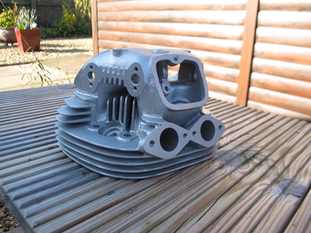
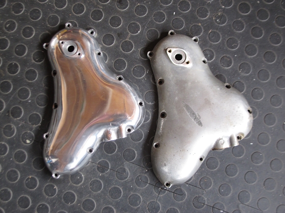
I also had a look at the complete engine that came with the bike. Even with a casual glance, it was easy to tell that the cylinder head had been mucked about with. When I bought the bike, Ted did tell me that he'd bought the engine from someone in Scotland and that it had been "tuned for racing". The inlet ports and carburettor spacing block, which should have had a bore of 1.1/8" as standard had been opened out... and not very well. The bores were no longer circular and no longer quite where they should be, and were much too large... very close to 1.3/8". Hmm... Amongst the bits I've got are a pair of 30mm bore Amal Mk 1 Concentric carburettors. As these are only very slightly larger than the 1.1/8" standard bore, I'd deemed them close enough to use, but there was no way that they would work correctly with the modified head. Time for Plan "B". Also amongst the bits was a second cylinder head. This, apparently was the head that came from the original engine. It was very grubby, like the crankcase, but it looked sound. It had been completely stripped. There was no valves, valve guides or rocker assemblies. Come to that, there were none of the studs in the head either. It was however, as far as I could tell, completely standard. Tomorrow morning, I'll drop it in to T & L Engineering on the way to the Strathmore Arms. They are going to acid dip it to remove any carbon build up, vapour blast it to clean the surface and inspect it for cracks etc. Barry has said that they will do their best to have it finished and ready for me to collect later in the afternoon on my return journey. Ya gotta love service like that!!
Tuesday, 4th April, 2023.
 Barry did indeed have the cylinder head ready and I collected it on my way home. It looks a lot better than it did when I left it with him. The good news is that it seems to be perfectly serviceable, so it looks like this is the head I'll be using. I will need to source new valve guides, valves and springs, but I'm hoping that the rocker assemblies in the modified head will transfer into the standard head without any problems. I won't know for sure until I start taking that engine apart.
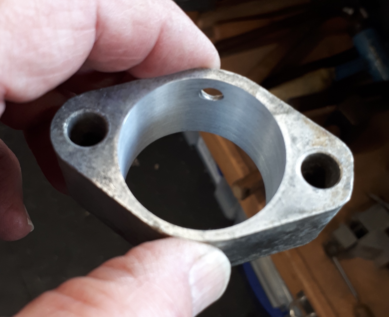
The bike build is coming together. I've identified a number of parts that are missing and I've started to source them. The rear brake pedal and associated bits are now in place, I've also found a head steady and the frame covers that were missing. I've also bought some stainless frame studs and nuts to replace the rusty items currently holding things in place. There is still a lot to do however. The inlet spacers that had been "tuned for racing" have been bored out to centralise the inlet tract. I've turned up two new sleeves that have been pressed in and they have been bored with a 2° taper. They are now 1.1/8" diameter on the side that mates against the cylinder head and 30mm on the side that the carburettors mate against. That gives a smooth transition with no steps.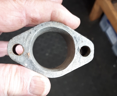
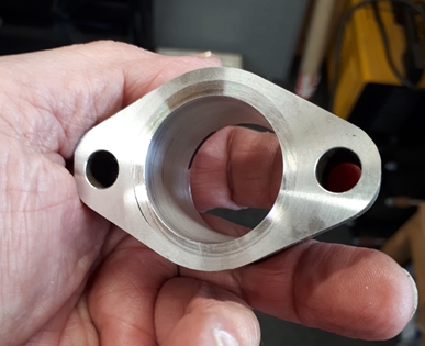
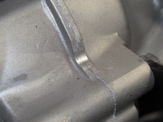
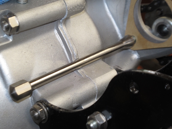
The balance pipe stubs had been cut off with a hacksaw at some point so I'll turn up a couple of new ones. I have some 10mm A/F hexagonal stainless steel bar that will do admirably. I'll be able to use them to balance the carburettors with vacuum gauges when the time comes.
Wednesday, 5th April, 2023.
It's "Good news, Bad news" time... The good news is that I've pretty much got the rolling chassis sorted, as far as components go. I've now either got all the bits I need or know where I will be getting them in due course. I've not dismantled the front forks or wheel hubs yet but at least I know that all the bits are there. The bad news is the 'donor' engine is perhaps not in as good a condition as I hoped. Today I got the engine up onto the bench and into the stand that I made for it a few weeks ago. The cylinder head nuts and bolts were only done up finger tight so the head came off relatively easily. First problem... There are no valve pushrods... Hmmm. Amongst the bits that I bought from Ted was a plastic bag with four pushrods in. I thought they were 'spares' but it seems not. They are 'different', though. The standard ones are an aluminium tube with steel caps on the ends. The ones I have are machined from solid aluminium. This engine, according the bloke that Ted bought it from, has been 'tuned for racing'. More about that in a minute. It could be that the solid pushrods would be a better bet for racing. Anyway, I'll probably use them when the time come to rebuild the engine into the correct crankcase. I had to make up a tool to draw the rocker spindles out of the cylinder head but that was simple enough, a short length of steel tube and a piece of studding to fit the thread in the end of the spindle. The rockers have been lightened and smoothed off in true "Café Racer" style, another nod to racing. Fortunately, the spindles and rockers all seem to be in very good condition with no detectable wear in the bushes. Not so the head. At some time the spindles have been punched into the cylinder head further than they were meant to go. This has resulted in the head casting being broken. It's a good job I have a better one which I'll be using. This one is not much more than scrap, now.
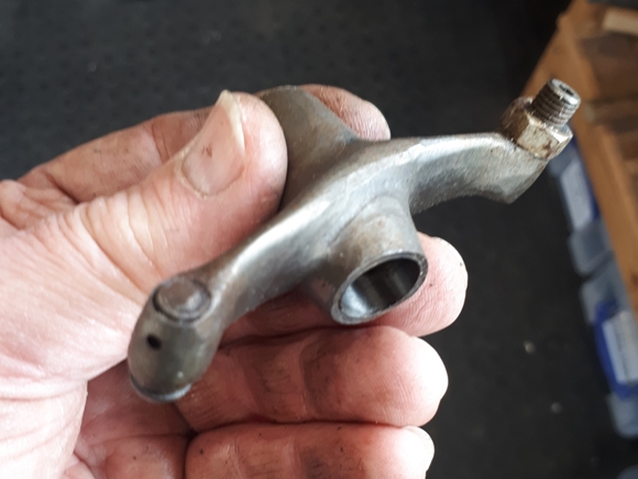
The steel valve spring retaining caps have been replaced with a set of aluminium ones, another nod to racing, reducing the reciprocating weight allowing the engine to rev higher without the valves bouncing. The valves are in very good condition, in fact, the pair on one side are new and have never been run. The ones in the other side have only had minimal running. There is no wear on any of the valve stem ends. I will probably re-use them. I will, however, use new valve springs. I have no idea how long this set has been sitting compressed.
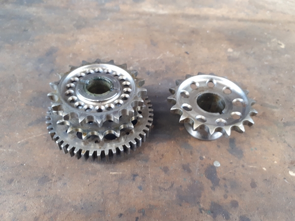
With the head stripped and put to one side, I looked at the timing cover. I removed all the screws... very few of which were original; one even being the wrong thread completely, but it had been screwed in anyway. This engine has not always had the TLC that it deserves. With the cover removed it was obvious that the camshaft sprocket and the intermediate gear/sprockets had also been lightened and polished. I can live with that. What I'm going to have trouble living with is that the automatic ignition advance unit on the magneto has been brazed up to make it inoperative. Fortunately, I have another that looks to be in good condition.
Sunday, 9th April, 2023.
On further examination, I found that the intermediate timing gear has a broken tooth. Fortunately, there were number of them available on t'interweb and I've acquired a replacement for a few quid. It's not lightened and polished , but hey... so what. The rest of the engine has been stripped. More bad news and not a lot of good news, I'm afraid. The cylinder barrels have been bored out to the maximum +0.060". I've checked the bores with a Mercer Bore Gauge and there is about 8 thou difference in the bore diameter between the unworn bottom and the worn top. That means a trip down to T & L Engineering to have them sleeved. Also going down to T & L will be the cylinder head as I want the barrels sleeved with spigotted liners to match the recesses in the head. They will need the head to ensure that the spigot fits correctly. Last but not least, the crankshaft will be going as well to have the sludge trap cleaned out. The oil holes in the big end journals were completely blocked with hard grey sludge. I did attempt to split the crankshaft myself but it was too tight and I don't really have the necessary tools.
The camshaft is the last of this batch of bad news. It's obviously an after-market re-grind and meant for racing. It would be totally unsuitable for gentle road riding!!
The only good news is that I have offered a good "X2" camshaft, as would have been originally fitted to the later model 650SS, at a reasonable price. As I type this, I'm waiting for a phone call from the guy who currently has it.
Tuesday, 11th April, 2023.
Easter has been and gone... Nobody bought me an Easter Egg... Bummer!! I have, however, been enjoying(?) myself in the workshop. I've managed to acquire, or at least, they are en-route from America, a lovely new pair of tank badges. These aren't your cheap chrome plated cast "monkey metal" jobs that Norton (and just about every other manufacturer back in the day) fitted. These have been cast in brass and given a proper, 3 layer, concourse chrome plated finish. 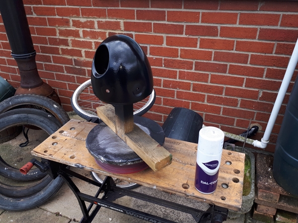 They were certainly not cheap, but they will look fantastic on the tank. Speaking of which, the tank is now in the hands of a company in Kempston that specialise in classic vehicle fuel tank and radiator restoration. They've had a look at it and pronounced it good for further work, so they will clean it, inside and out, line it with an ethanol proof epoxy sealant, and finally a coat of red oxide primer on the outside. I'm fairly certain that Kristian Vere, at Lutton Body Shop, will be able to do the tank justice with a coat or three of silver grey paint and clear lacquer.
Talking of painting, I've been assessing the headlamp and associated bits and pieces. The shell is very sound, and undented so I'm proposing to use that in the restoration. The chronometric speedometer is mounted in the headlamp shell, along with the light switch and an ammeter. More about those parts later. The early 650SS bikes didn't have a tachometer, that came a little later and was mounted on a bracket that was, in turn, secured under the right hand front fork leg cap nut. It looked exactly what it was, a bolted on after-thought, but that's the way they were. Subsequently, on the later models, the speedometer and tachometer were both mounted on a single plate across the top of both fork legs. Going back to the headlamp shell, I've cleaned most of the rust off with a flap wheel on the bench grinder. I have some black etch primer and have given it four or five coats of thet. I'll leave it for a couple of days to thoroughly dry, then cut it back with wet and dry paper. I have some hi-build primer which I apply to take out the last of the imperfections, before applying a jet black base coat followed by clear lacquer. Hopefully, it will turn out ok and I can save a few quid by doing some of the other smaller part.
The last thing I did today was to drop out the rear wheel and strip the brake plate. That, like all the other metalwork, is black, dirty and has surface rust, but it's basically sound underneath. I'll need a new back brake drum / sprocket as this one is very badly worn... to the point where a tooth has actually broken off. I'll probably get a new pair of brake shoes as these are the old asbestos compound and modern materials are much better.
Friday, 14th April, 2023.
 The new tank badges were delivered by DHL this afternoon. The good news... they look superb, but I won't know how well they fit the shape of the tank until I get that back from Kempstone Radiators. The bad news... one of them was damaged. It had taken a blow on the front pointed end and that was bent at right angles. Being cast brass, it was broken, and any attempt to straighten it would have resulted in the end snapping off. It was packed extremely well, with no obvious sign of the package being damaged by dropping so I suspect that it might have been dropped before being packed. I contacted the vendor, Donald Pender, who was understandably shocked. There was no quibbling, he is sending a replacement on Monday. I like the American attitude that customer satisfaction takes priority.
The replacement intermediate idler gear has arrived and that looks fine, as does the replacement X2 camshaft that has also arrived. I'm pleased with the way the headlamp shell has come up. I flatted the primer back, almost to the metal and the vast majority of the imperfections have been filled. I've now given it another five coats of hi-build primer and will let that dry thoroughly before flatting it again and applying the jet black base coat and then the clear gloss lacquer. All the paint I've used is K2 aerosol from Advanced Paints in Chippenham.
Sunday, 14th April, 2023.
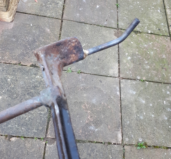 Just a quick update... I've given the headlamp shell a couple of coats of black base coat. That will need flatting off and the clear gloss lacquer applied. I've also repaired the centre stand. The extension on the left hand side had been snapped (or cut?) off at some point in the past. That has now been re-instated.
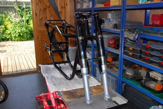
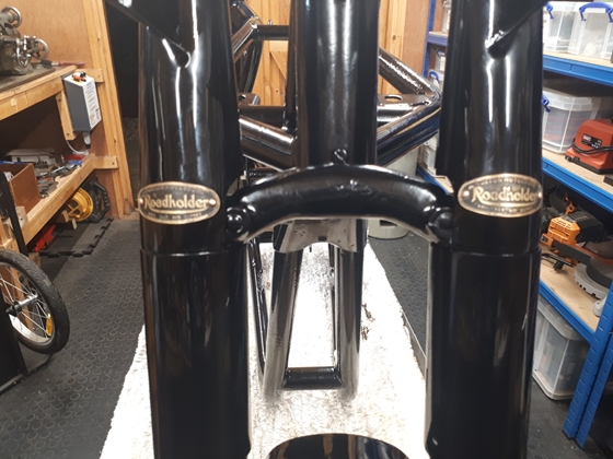
I've completely stripped the two front fork legs. On the whole, they aren't too bad. The stanchions aren't anywhere near as pitted and rusty as I'd expected, which is good news. The bushes are good and won't need replacing. However, one of the damper tubes has been badly 'abused' and will be replaced. The oil seals I'll replace as a matter of course. The chrome plated slider extensions are too rusty to reuse and it's cheaper to by new replacements than to have the originals re-chromed.
The two yokes (triple-trees if you're American) are straight and true. They will be powder coated and re-used. The bearings are interesting. I was expecting to find the usual cups and loose balls but someone has replaced the original bearings with a pair of single row, angular contact ball races. These were well greased and in excellent condition. The very rusty steering stem top nut and the two fork leg cap screw are cheap enough and will be replaced with stainless steel items.
I've sorted out which parts are going to CWC for powder coating, which parts will be taken to Breckland Finishing, and which parts I'll be taking to Lutton Body Shop. If the headlamp shell turns out well, I may also try a couple of other simple parts myself.
Sunday, 14th April, 2023.
The headlamp shell turned out ok. Certainly good enough to use. I've taken a load of the small bits and slightly "less important" parts down to Richard at Breckland Finishing. I've also taken the crankshaft and swinging arm to T & L Engineering. The former to be split and the sludge trap/filter cleaned. I've left a complete set of new studs and bolts with him for the re-assembly. The latter, to have the "Silentbloc" bonded rubber bushes pressed out. Once it has been powder coated, I'll put in new bushes.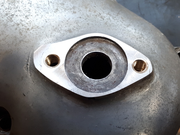 I've been round to see Kristian Vere at the Lutton Body Shop and left some parts with him; namely the primary chaincase outer cover, the two upper fork shrouds / headlamp brackets and the two lower fork shrouds. Hopefully, I'll get them back in due course painted gloss black.
Back in the workshop, I've been looking at the engine timing cover and tachometer drive gearbox. That has also suffered at the hands of a previous owner at some point. The tachometer drive has two, 1/4" diameter, counter-bored fixing holes. The timing cover has two, 5/16" BSF tapped holes... Hmmm. The tacho drive was held in place with two 1/4" UNF bolts and nuts on the inside that had been peened over to secure them. Not an altogether satisfactory state of affairs, so I've turned up two threaded brass bushes which have been screwed into the timing cover with Loctite 638 high strength retainer. They will not be coming out anytime soon!. These bushes have been drilled and tapped 1/4" BSF and the tacho drive gearbox will now be secured with two, 1/4" BSF stainless steel cap head screws. Only two other things of note at the moment... I've sent two of the three magnetos that I have down to Paul Wolf in Devon. He will rebuild the "Competition" K2F and take the other "ordinary" K2F in part payment. Also, the chronometric speedometer has been sent to Russell at Chronometric Instrument Services for a "concourse" restoration. I will, at some point, need to obtain a matching tachometer, but that will be some way off yet.
Saturday, 29th April, 2023.
Ok... Things are progressing but the progress has slowed somewhat. The rebuilt K2FC magneto has come back from Paul Wolf and I'm happy to say that I get a spark from it on both outputs. It also looks a bit better as it has been cleaned. That will be put to one side for now and is ready to go back on the engine when the time comes.
This morning, the rebuilt speedometer came back from Russell at Chronometric Instrument Services. He has, as usual, done a great job. Everything has been replaced and it is, to all intents and purposes, a brand new speedometer. He's also supplied a new drive cable at a very competitive price. Like the magneto, this will now be put to one side until needed.
The crankshaft and swinging arm are still with T & L Engineering. I 'phoned them earlier in the week and I'm expecting to be able to collect them sometime in the coming week. As yet, I've not heard from Kristian at The Lutton Body Shop but he did say it may be a while before I heard from him. To speed things up a bit in the future, I looked for, and found a place fairly locally (about 1/2 hour's drive away) that will media blast parts for me... Rockcliffe Shotblasting in Watlington. I visited them yesterday and left the two worst parts with them... the very rusty mudguards. If they can clean them satisfactorily, I'll let them have the oil tank and tool-box to clean before giving them to Kristian for painting. That should make his life easier and reduce the cost a bit.
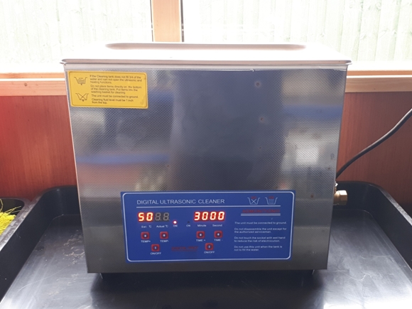
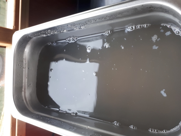
I've acquired a new bit of kit... An ultrasonic cleaning tank. It was surplus to requirements at The Two Wheel Centre and Nick very generously gave it to me. I'd already stripped the two Amal Concentric carburettors that I intend using and they were available for testing the cleaning tank. I thought they were already pretty clean but I was gob-smacked at how dirty the cleaning fluid was after 30 minutes at 55°C. It very definitely works!!
Tuesday, 2nd May, 2023.
I've hit a snag!! A few weeks ago I assembled the gearbox, using what I thought would be the best parts of the two gearboxes that came with the bike. That was the case and internals from the numbered earlier box with the inner and outer covers, kickstart shaft and spring from the later, un-numbered box. It all went together ok but when I offered it up in the engine plates a while back, the clutch cable entry in the outer cover was in the wrong place, and fouled the bottom of the oil tank. Ok, not a disaster, it just meant that I would have to replace the outer cover with the older one which had the cable entry in the correct place. Today was the day to do just that. Then I hit the snag... the older outer cover wasn't compatible with the newer kickstart shaft and spring so I had to change them as well. That meant also changing the inner cover. Ho hum!!
Sunday, 7nd May, 2023.
I've been down to Breckland Finishing to collect the black powder coated parts I left with them a while back. It all looks good and has been put away until needed. I've also had a phone call from Kempston Radiators to let me know that the petrol tank has been cleaned, media blasted, lined and given a coat of primer. I will be heading south for a few days on Wednesday so I'll pick it up on the way.
Monday, 15th May, 2023.
I've got the tank back and it looks a lot better than it did when I left it with Kempston Radiators. It's clean inside and the outside has been given a brushed on coat of what looks a bit like silver Hammerite. The rust pitting on the surface is still just about visible but I'm pretty sure that when it's been rubbed down and given a few coats of high build primer it will look even better. I'll drop it round to the Lutton Body Shop at some point in the future for finishing in the gloss silver-grey paint. The new tank badges that I bought from Donald Pender in The States look like they will fit ok, which is good news.
The bad news this time is that I've had a phone call from Barry at T & L Engineering. He's split the crankshaft and cleaned out the sludge trap but he recons that the big end journals need a re-grind. I'm OK with that and have told him to go ahead. It's only money!!
Wednesday, 31st May, 2023.
Just a quick update... Will at Rockcliffe Shotblasting phoned yesterday to say that the mudguards are ready for collection. I collected them this morning and took the straight round to Kristian at the Lutton Bodyshop. As they are now just raw steel and prone to rusting again, they will need a coat of primer to stop that happening. Kristian showed me the new bead blasting cabinet that he's bought, so he'll be able to do that now rather than me outsourcing it separately.
Tuesday, 27th June, 2023.
 I've collected the crankshaft and swinging arm from T & L Engineering. As usual, they've done an excellent job. I had a word with Barry while I was there about the sleeving the cylinder barrels. Although the barrels I would like to use are for a later model without the spigot for the cylinder head, Barry can use a spigotted liner so that they will match the earlier cylinder head that I would like to use. That's potentially good news as it means that I won't have to modify the earlier cylinder head.
I've ordered new big end shells and new main bearings from RGM. Main bearings are a bit confusing as they were changed a few times during the production life of the Norton twin cylinder engine. I've opted for a standard ball bearing on the timing side, as that seems to be the bearing of choice and a "Superblend" roller bearing on the drive side as this was fitted to the later engines and is supposed to reduce the risk of crankshaft failure. I seem to have spent a lot of money, and so far have little to show for it apart from boxes of bits. I'm now in a position, however, to take the frame and a lot of other bits for powder coating. When that's done, I can start on the assembly and the project will have moved on to the next stage.
Friday, 7th July, 2023.
Friday, 21st July, 2023.
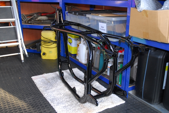
OK... I've not been totally idle in the last couple of weeks. The frame, rear fork etc. have been taken across to CWC for powder coating. Chris (the guy behind the counter) said that lead times have reduced considerably, and it may be as short as seven days. Well it wasn't. It's been 10 days and I've not heard from them, but hey... I've got the rest of my life to finish the project, so no hurry. Hang on a minute... I'm 77. Best get your fingers out, gentlemen!!
I've also been in touch with Kristian at the Lutton Body Shop. There was a little confusion about waiting for me to take them some more parts, but that has now been sorted and hopefully, it won't be too long before I get some bits back from them.
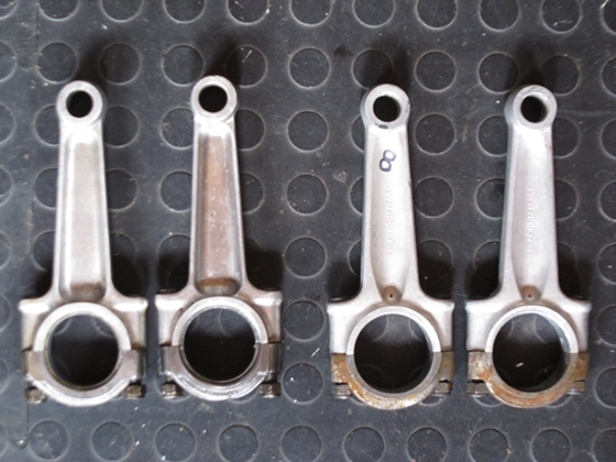
Back up the page aways, I mentioned repairing the tachometer drive mounting threads in the timing cover. For whatever reason, a previous owner had opened them up to 5/16" and tapped them. I made threaded inserts to bring them back to a sensible size. Well, I saw on a Norton owners Facebook page that there was a good one for sale. I contacted the owner, Nigel Gibson, and the cover is now in my possession. It's polished, undamaged and in all round better nick that the one I had. I also relieved him of a new set of valve springs and a good, useable oil connection block/pipes. It was while I was talking to him on the 'phone that we discussed the pros and cons of the 3 or 6 start oil pumps. I seem to have a mixture of bits, unfortunately. The oil pump is a 6 start, high output pump. The connecting rods are earlier ones, as used with the 3 start pump, and don't have the oil pressure relief holes in them that were introduced with the 6 start pump. Also, the valve rocker spindles have the spiral oil lubrication groove ground into them that was used with the 3 start pump. It is pretty essential, so I'm told, that to avoid "over oiling" the valve gear, that plain spindles are used with the 6 start pump. With all that in mind, I've managed to acquire a pair of later connecting rods with the oil pressure relief holes. They are of a slightly stronger design and were used in the later Atlas and Commando engines. That just leaves the valve rocker spindle problem. I have two options, it seems. I can source four new plain spindles and use the high pressure oil connection in the timing cover to lubricate the valve gear, or I can revert to the low pressure oil connection on the oil return adaptor on the oil tank to lubricate the valve gear. Both options are valid and I think that I already have an oil tank adaptor somewhere in one of the numerous boxes of bits.
Thursday, 3rd August, 2023.
A couple of thing to up-date you on... I've obtained a set of plain rocker spindles, so I will be using a 6 start oil pump and the high pressure feed to the rockers. Time will tell if I've made the right decision.
Yesterday, I had a 'phone call from CWC to say that the frame was ready for collection. This morning I drove over to Coleshill handed over a fistful of wedge. To save another journey, I took the rear wheel hub up with me. That will be powder coated silver and have a valanced aluminium rim built on. That will be shod with an Avon SM MK11 tyre with a Michelin inner tube.
Kris at the Lutton Body Shop also contacted me this evening to say that the bits that he's painted are ready. They will be collected tomorrow and another significant chunk of wedge will be leaving my bank account... Ho hum!!
Friday, 4th August, 2023.
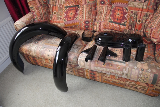
 This morning I collected the painted tinware from Kris at the Lutton Body Shop. What can I say... that bloke is amazing. Considering the rusty, pitted steel that he started with, the results are amazing; the photo just does not do justice to the quality of the paintwork. It wasn't cheap but I would have paid more if he'd asked for it.
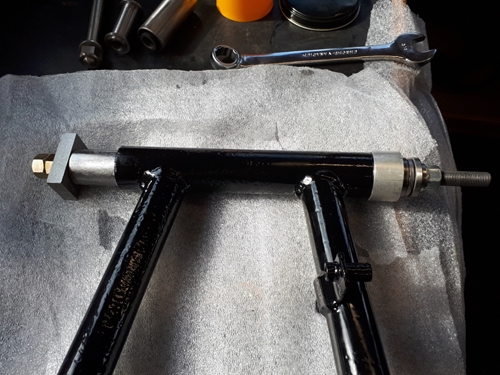
As I'd got the swinging arm back from CWC yesterday, I guessed it was about time to see if the tool I'd made to install the metalastic bushes actually worked. Happy to say that it did. I'd lightly sanded the outside sleeve of the bushes and the internal bore of the fork. I greased both the bush and the bore and wound the first bush in. It went in with less agro than I expected although it did get progressively tighter as it went in. With the first bush installed so that the outer sleeve was flush with the fork tube, I used the same method to install the second bush and spacer tube. That went in flush as well. Happy to say that it was a lot less stressful than I been led to believe.
Monday, 7th August, 2023.
Just a quick update... This morning I took the two aluminium fork sliders and the three aluminium rocker covers down to T & L Engineering to be vapour blasted. That's the last of the vapour blasting and means that I can assemble the forks into the frame. Hopefully, I'll be able to pick them up on Wednesday.
Monday, 28th August, 2023.
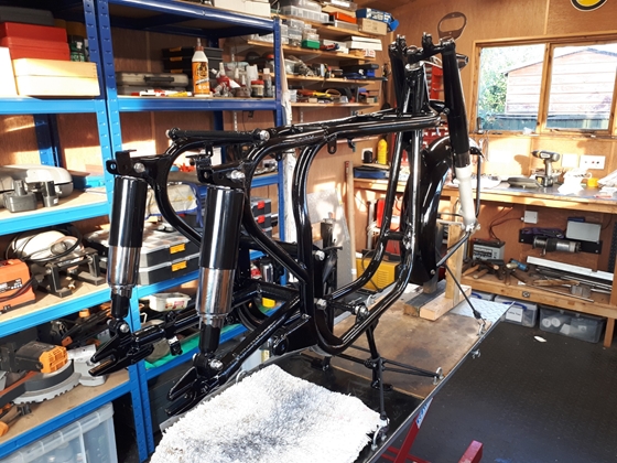
A significant milestone in the restoration of this Norton has been reached. The frame is in the workshop, and I now have a "chassis". It's not rolling yet, but hopefully it will be before too long.
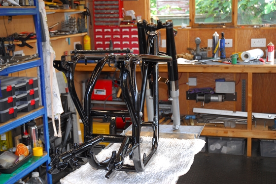
The rear swinging arm fork has been assembled to the frame but has not yet been fully tightened. It needs about an inch of "pre-load" and I can't do that until I've got the new rear suspension units, which have been ordered but they've not yet arrived.
Thursday, 7th September, 2023.
Some parts that I'd ordered have arrived and been fitted. The major parts are the two rear suspension units. They came from Andover-Norton but weren't exactly right. They were supplied with two different length steel spacer tubes for the top mounting but even with the longer tube fitted, there was still room for two flat washers each side to make it up to the correct length. No big deal in the great scheme of things but I had expected Andover-Norton to supply the correct bits. The other part was the mounting bracket for the tachometer. This is secured under the right hand fork cap bolt. With that in place, I could attach the damper rods to the cap bolts and pour in the correct amount (150ml) of SAE20 fork oil. Easier said than done as there was very little clearance for the oil to drain down. In the end, I had to remove the springs, pour in the oil and then re-assemble it all again. Ho hum.... You live and learn!! The centre stand has been fitted with new pivot bolts and the front forks supported on a couple of wooden "axle stands" that I made originally to support the Matchless G80CS. Finally, as far as the frame goes for the moment, the front mudguard has been offered up and fitted with the old bolts. I thought I got new ones, but apparently not, so they are now on the way.
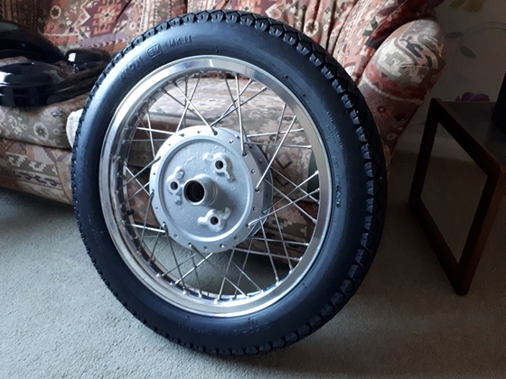
Yesterday, I had phone call from CWC to say that the rear wheel was ready for me to collect. Today, I drove west to Coleshill to collect it. The hub has been blasted and powder coated silver... It was painted silver originally. That has turned out better than I expected, given the rough state that the hub was in when I left it with them. The Borrani valanced aluminium rim looks great and is a nod to the old Café Racers, back in the day. It's been fitted with a new 3.50 x 19 Avon SM Mk II tyre and a Michelin tube. That little lot wasn't cheap but hey, it's only money!!
Tuesday, 12th September, 2023.
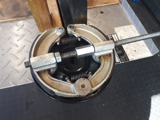 I've had a delivery of parts I needed to complete the rear wheel. The most significant being a new brake drum/sprocket. There was also a new stainless steel spindle with nut and spacers and a pair of stainless wheel adjuster screws. The bearings that I took out are in perfect condition so they were just cleaned, packed with grease and put back into the hub. The biggest problem I had was installing the new brake shoes onto the brake plate. With both shoes and the expander cam in place, I could get the spring nearest to the pivots on but there was no way I could stretch the spring nearest the expander cam anywhere near enough to get it fitted over the locating hooks on the brake shoes. Time for a little creative thinking. If I removed the expander cam, the shoes came together close enough to fit the spring, but then I couldn't spread the shoes against the spring pressure far enough to refit the expander. A search amongst my boxes of assorted stuff I rarely use, and I came up with a pair of old coil spring compressors, meant for compressing car suspension springs. I turned the hooks on one of them around and found that they fitted inside the brake shoes. I used that to expand the brake shoes far enough to refit the expander cam. Yea... the job's a good 'un!!
Tuesday, 19th September, 2023.
 Not a great deal done in the last week. Real life sometimes gets in the way. The polished stainless mudguard fixing bolts arrived and the front and rear mudguards have been fitted properly. When I trial fitted the engine and gearbox, back in March, there was a minor problem with the engine plates. There are two bolts that secure the rear of the engine plates to the frame, but I could only get one of them in position. The holes in the engine plates didn't quite line up with the holes in the frame. It was only a few thou. but enough to stop the bolts going through. That has now been addressed and the plates fit correctly.
The rear wheel has been installed into the rear forks. It will have to come out again at some point when the bikes wiring is installed but for now it's in position and looks good. The more knowledgeable amongst you will notice that the rear hub is missing it's polished alloy cover on the right hand side. That's deliberate. I didn't like it much as it looked odd with the silver painted hub casting. Now the hub has been powder coated and the sprocket / brake drum bolts have been replaced with stainless steel ones, it looks good enough to leave as it is.
Thursday, 21st September, 2023.
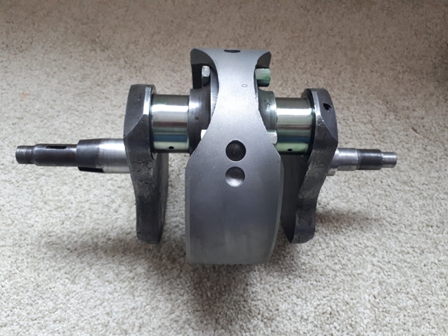
It's been hot in the kitchen today. The time had come to start assembling the engine, or at least, the bottom end. First, the new main bearings. As a general rule, I tend not to hit things with a hammer unless they're nails. Driving bearings onto crankshafts and into crankcases with drifts and hammers is not the way I like to do it, although it is often the "accepted" method as at room temperature, they are interference fits. The timing side main bearing is a standard single row ball bearing. On the drive side, it's a two part "Superblend" roller bearing. The outer ring and rollers are one part; they go into the crankcase. The inner ring is separate and goes onto the crankshaft. So it was the crankshaft that I started with. That went into the bottom drawer of the freezer at -18°C. The timing side ball bearing and the inner ring of the drive side roller bearing went into the oven as 180°C. They stayed there for approximately 30 minutes. I set up the "Workmate" in the kitchen in readiness. The crankshaft came out of the freezer and was placed on the workmate, drive side axle uppermost. The hot roller bearing inner ring was dropped over the axle with a satisfying "ding" as it stopped against the shoulder on the crank web. Perfect. That rapidly cooled and remained in place when I turned the crankshaft over. The hot ball bearing was placed over the timing side axle and it dropped into place. Also perfect!!
Now it was the turn of the crankcase. The drive side half went into the oven, whilst the outer ring and rollers of the Superblend bearing went into the freezer. Half an hour later, the crankcase was placed on the workmate, and the roller bearing dropped into its location. A light tap with a piece of wood ensured it was seated correctly while the case cooled down. The timing side would wait until the connecting rods were in place.
Friday, 22nd September, 2023.
First things to tackle this morning were the big end bearings. The crank was meticulously cleaned and blown through with compressed air. I cleaned the connecting rods and big end shells then applied a liberal coating of Permatex "Ultra Slick" assembly lubricant before fitting them to the crankshaft with new big end bolts and nuts. They were tightened to 25 lb/ft of torque. The connecting rods rotated around the crank smoothly and without any "slop", just as they should on a newly re-ground crank. At this point, the the timing side crankcase half went into the oven. As well as the bearing, there was a new intermediate timing gear spindle to install.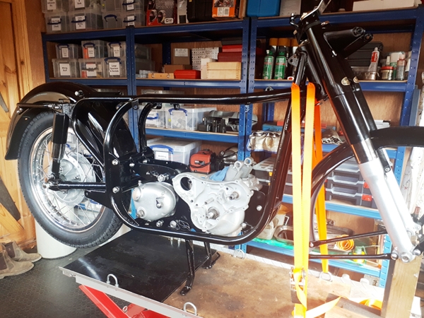 The went into the freezer. The procedure was pretty much as before. The case placed on the workmate face down and the new timing spindle pushed into position with the oil hole in the correct orientation. It was tapped lightly with a piece of wood to ensure it was fully home. That lot went back into the oven briefly, while the crankshaft was set up with the timing side bearing uppermost. The hot case was placed over the bearing and it dropped into position. It was also tapped lightly with a wooden block to ensure it was seated correctly over the bearing. That's it, new bearings installed with the minimum of fuss. Hammer and drift not needed. Now it was just a case of bringing the two halve of the crankcase together, with the camshaft in position, of course. I had all new stainless nuts, bolts and studs ready to hand. I didn't want the crankcase to leak oil once it was assembled so the joint face of both halves I painted, quite literally, with "ThreeBond" sealant. With the timing side supported on wooden blocks, the camshaft and breather disc valve, were lubricated and put in position, then the drive side crankcase half was lowered over the crankshaft and the two halves of the crankcase held together with the studs and screws not used to attach the engine plates.
The rear engine plates were loosely bolted to the assembled bottom end and the whole lot offered into the frame. With a little jiggling, I managed to get all the fixings and the front engine plates into position. The centre stand spring and it's anchor pin were next, followed by the gearbox I rebuilt some time ago. When I was happy that all was well, the fixings were all fully tightened.
Thursday, 28th September, 2023.
Although it doesn't look like it, a lot has happened in the last week or so. First, I realised that the anchor bolt for the centre stand spring wasn't in the correct location. It needed to be in a different hole in the left hand engine plate, one that was 2" higher. That made installing the spring somewhat difficult as the tension was ... ummm... significant!!
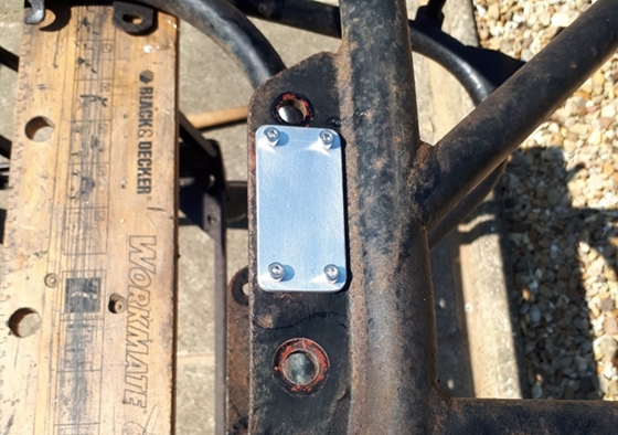
Having posted a photo of my progress on the Norton Owners Club forum, I received two important pieces of advice. The first, regarding the nuts that secure the magneto, specifically, the lower of the three. With the magneto in position, it's almost impossible to fit that nut and then get a spanner on it in order to tighten it. The second was something I hadn't thought about. A side stand. Back in the day, there wasn't one fitted, but after market side stands are now available. I was advised that they need to be fitted before the primary chain case is installed. That meant now. So with that in mind, I ordered and have received an extended magneto nut and a side stand kit from RGM Norton Ltd.
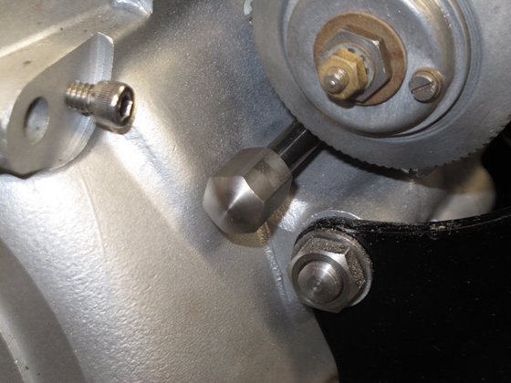
The stainless steel extended magneto nut looked good but I needed to remove a little of the crankcase joint flange with the Dremel to give enough clearance for the waisted part of the nut to line up with the stud. That done, the magneto was fitted with relative ease. I took it off again as I wasn't ready to set up the ignition timing. That would be done once the cylinder barrel and pistons were fitted.
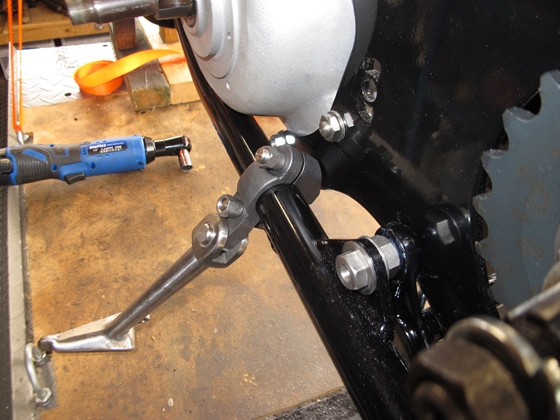
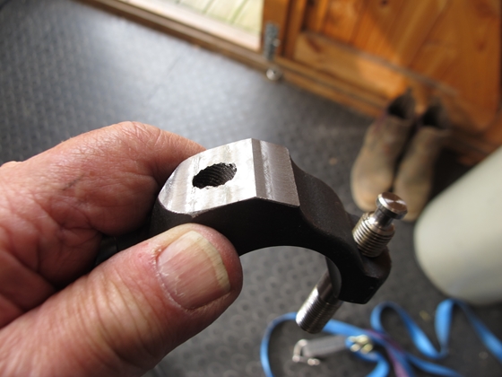
 The side stand from RGM is a substantial piece of kit but fitting it isn't without it's problems. It's designed to be clamped around the left side bottom frame tube and up against the left hand engine plate. Unfortunately, there wasn't room to get the inner half of the clamp in position. The fitting instructions state that some "fettling" may be needed. That fettling, in my case, meant that a significant amount of steel had to be removed. There was no way I was going to file it all off, so I set it up on the mill and removed it that way. I didn't want to remove too much so I took a couple of cuts then tried it on the frame. Eventually, I'd removed just enough to enable me to fit the clamp around the frame tube with the side stand in a what looks like a sensible position. I won't know for sure if it's in the correct position until I've got the front wheel in and can give the bike a "test lean". It may still need some adjustment. I had thought to get it powder coated but in light of it possibly needing more material removing, I'll give it a coat of paint. That way, I can always repaint any area that need to be modified. Now all I have to do is figure out how to get the very strong spring back in position without incurring significant personal injury!!
Thursday, 12th October, 2023.
Decisions have been made and some more, yet to be made. I knew this build was going to be a challenge, but when I bought the bits, I really didn't know how much of a challenge it was going to be. The rolling chassis is not a problem. That's been pretty much straightforward; it just needed the parts bringing together. It's the engine that has been the biggest headache. I had the cylinder head and crankcase with the number that matched the frame; and I had a donor engine. That engine was a mixture of parts from different years and it's that that is causing the problem. The crankcase dates from early 1963. Three or four years later, Norton introduced a significant design change. The oil pump drive gears were changed from a 3 start worm gear to a 6 start worm gear. This doubled the speed of the oil pump and consequently the quantity oil it pumped around the engine. At this point, the feed to the rockers in the cylinder head was also changed, from a low pressure feed from the oil return line to a high pressure feed from a tapping in the timing cover. To cope with the extra oil being delivered to the cylinder head, the oil passages in the crankcase were enlarged, the oil delivery and feed pipes, and the oil junction holes were also enlarged. The connecting rods were changed and have a small "relief hole" in them to bleed away some of the excess oil.
Anyway... to cut a long story short, I can't use the 6 start oil pump with my crankcase as there will be a serious risk of oil building up in the cylinder head and causing all sorts of problems. I have to use all the components of the earlier 3 start oil pump system. Which means I may have to split the crankcase again to change the connecting rods to the earlier version without the oil relief hole. Buggeration and fuckery.
Thursday, 26th October, 2023.
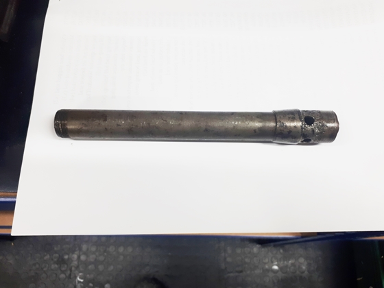
Bullets have been bitten and things have changed. First off, a replacement oil pump has been sourced. The one that was bolted to the donor engine was deemed un-useable as for some reason, on that donor engine, the 5/16" mounting holes in the pump had been opened up to 3/8" and the crankcase drilled and tapped 3/8" BSF. The new pump has the original 5/16" holes to fit the studs in the matching numbers crankcase I'm using. I've also bought a new set of 3 start drive gears for that pump. So far, so good. I've had a look at the rockers and scrolled spindles and they are in good condition, so I'll use them and put the new plain ones I bought up on Ebay. I have the correct oil tank return fitting to feed the rockers, so that will be used and a blanking plug put in the timing case high pressure tapping. Finally, the engine has come out of the frame again, been stripped and the older, un-drilled connecting rods fitted. Again, the later connecting rods will be sold on to help with the cost. Now I have to put the whole lot back in the frame again.
Sunday, 19th November, 2023.
Just a quick update... The front wheel has been collected from CWC and fitted into the forks. That was not without it's problems, however. The bike would have originally been fitted with a 3.00 x 19" Avon Speedmaster front tyre. I thought I would be clever and fit a slightly wider 3.25 tyre. Not so clever after all as I soon found out that the clearance between the tyre and the mudguard stay bolts was marginal, to say the least. That took a set of shorter bolts and some subtle bending of the mudguard to overcome.
I've fitted new shoes to the front brake and they needed the "high spots" smoothing off before the wheel would rotate freely after fitting. I've also bought a very expensive AJS/Matchless brake lever yoke for the cable to fit in. The are machined from solid stainless steel and polished... so much nicer than the bit of bent steel strip that Norton fitted.
Wednesday, 6th December, 2023.
Just another quick up-date. Things have slowed down, mainly as I'm waiting for the cylinders etc. to come back from T & L Engineering. I phoned them a few days ago and hopefully, it won't be too much longer...
In the meantime, I've cleaned up the oil tank as best I can and have taken that, along with the tool/battery box and the headlamp shell to Kristian at the Lutton Body Shop. I did have a go at doing the headlamp with a rattle can, but the result was nowhere near as good as the finish Kristian got on the mudguards so I'll let them do it all.
Sunday, 10th December, 2023.
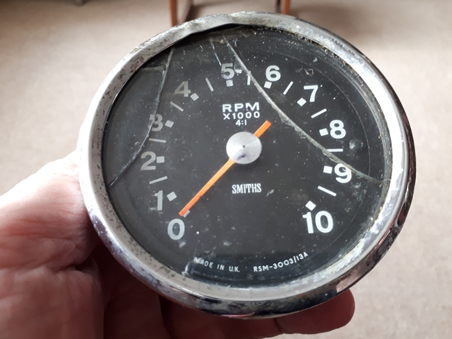
 I have a bit of a conundrum to solve. I would like to fit a tachometer but I don't have one. "Just go and buy one." I can hear you say, and you're right, I could just go and buy one... for £425, which is the price that Russell at Chronometric Instruments is asking for one. That's a lot of money, so are there any other options? Well, yes, there are a couple. Russell would allow £200 in part exchange for any Smith chronometric instrument, speedo or tacho, working or not working, provided that it is good enough to repair. So if I could find an old chronometric speedometer of tachometer for less than £200, I can save the difference. Problem is, people want silly money for them and I'm unlikely to get one for less that £300, so that's really a non starter. I could fit an electronic instrument, but that comes with it's own set of problems like fitting a pulse sender and an "ignition" switch. Alternatively, I could fit a magnetic instrument. I've found a modern reproduction instrument on-line that looks right, needs a 4:1 drive which I have, and is only £60. Got to be worth a punt!!
Sunday, 17th December, 2023.
Then I had another thought... There's a worrying trend developing here... me thinking!! If I'm happy to fit a magnetic instrument, possibly in the short term until I can source a chronometric tachometer, I really ought to fit a period correct Smiths magnetic tachometer. To that end, I've found one on-line for £50. It's damaged... the bezel has had a knock and the glass is cracked but I know a man who can fix that. Ashley Pople made a cracking job of restoring the magnetic speedometer on my Tiger 90, so I'll get in touch with him after Christmas and hopefully, he can do the same with this tachometer.
Tuesday, 16th January, 2024.
A month on and not much has changed. I've been in touch with Ashley Pople and he will repair the damaged Smiths tachometer. But... he will be away until the 20th January. I'll wait until then and post it to him.
I've also been in touch with Barry at T & L Engineering regarding the cylinder barrels and cam followers. He is working on them but I'm unlikely to see them before the end of the month. Ho hum!!
Tuesday, 30th January, 2024.
Well... Another new year and for once, a little progress, or good news at least. I sent the tachometer off to Ashley Pople a few days ago and yesterday, he phoned to say he'd received it and it would be restored and posted back to me soon.
I've also heard from T & L Engineering. Barry Talbot emailed me this morning to say that the work on the barrels and cam followers was finished and I could collect it. I've made arrangements to do just that on Friday. I'll also meet up with Les at the Strathmore for lunch.
Saturday, 3rd February, 2024.
Yesterday, I dropped into T & L Engineering and collected the re-sleeved barrels, new pistons and re-ground cam followers. Have I mentioned the cam followers before? Maybe not... Well as they came from the engine that had been used for racing, the cam contact face had been ground with a curved profile. The X2 camshaft that I've fitted was designed to work with flat profile cam followers. For that reason, they've been re-ground with flat profiles.
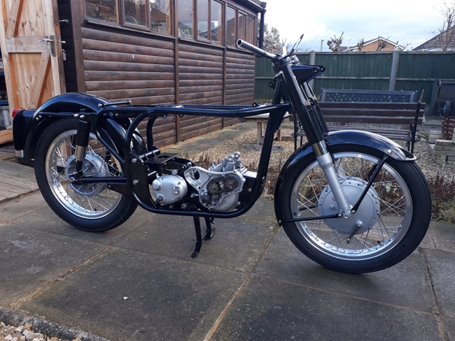 As a point of interest, Barry told me that the barrels had not been machined correctly at the factory. The base flange and the top face weren't parallel. When Barry bored them, they were bored perpendicular to the bottom face that mates to the crankcase. He found that the top face was about 0.005" out of parallel. In the great scheme of things, that's not a lot, but he's taken a light skim across the top to true it up.
I put the wheels into the frame quite a while ago so I had a rolling chassis, but this is the first time I've actually taken it off the workbench and wheeled it out of the workshop. I bought a side stand from RGM a while back and with some mods to the shape, fitted it to the lower frame tube. What I needed to know was whether it held the bike at a sensible angle when it was used. Happy to say that it does. However... there's always a "however" with my stuff... It doesn't fold back completely. I'm guessing that RGM made it that way so it could be fitted to suit individual bikes. It's easy enough to grind a bit off the relevant part but until I have the left hand exhaust pipe fitted, I don't know how much to remove, so that adjustment will have to wait!!
Thursday, 8th February, 2024.
I phoned Patrick at Seager Engineering this morning to confirm that it would be OK to drop the cylinder head down to him. It was, so I did. A relatively easy run down to near Stowmarket, in Suffolk. We discussed what should be done. I'd also taken the new valves, and associated bits as well. He will make and install new Colsibro valve guides, re-cut the valve seats and assemble the valves into the head. He will also take a light skim across the mating face to ensure that it's flat. It shouldn't take him long, hopefully!!
Sunday, 11th February, 2024.
The repaired tachometer has come back from Ashley and it looks great. I've obtained a new bulb holder that plugs into the hole in the back of the case. I had to modify the stainless mounting bracket very slightly to clear the edge of the bulb holder, but now that's done, the tacho sits down correctly on the mounting bracket.
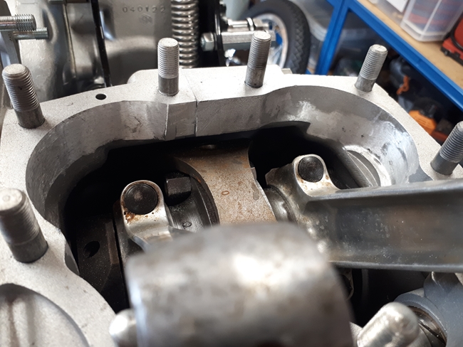 Now that I've got the barrels and pistons back from T & L, it was time to build up a bit more of the engine. Before I did that, however, I wanted to check that the barrels sat down on the crankcase correctly. Just as well I checked as they didn't. The barrels came from the donor engine and had never been on the crankcase I'm using. The short skirt on the barrels was jamming very slightly on a rough part of the inside of the crankcase casting. A few minutes with the Dremel soon smoothed off the rough spots and the barrel now sits down flush onto the crankcase as it should.
Time to fit the pistons. I'd already checked the piston ring end gaps and found that they were absolutely spot on. They were fitted onto the new pistons without any breakage, fortunately. The pistons needed to be warmed up a little to expand them enough to push out the gudgeon pins so that I could fit them to the connecting rods. The circlips were fitted very carefully and I didn't have them pinging out across the workshop. The cylinder base gasket 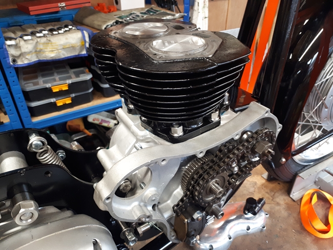 was sparingly coated with Hylomar on the underside and set down onto the crankcase joint face. The support 'table' that I'd made for the Triumphs needed a little adjustment but then fitted around the conrods and rested on top of the crankcase studs. I'd already sourced a pair of the correct size piston ring clamps so they were carefully fitted around the pistons after a liberal application of oil and the barrel slid over them without breaking anything. I'd coated the underside of the cylinder base flange with Hylomar. After removing the ring clamps and support table, the cylinder barrel was fitted down onto the crankcase and secured with new stainless nuts and washers.
Monday, 12th February, 2024.
Now comes the tricky operation of installing the magneto and setting up the ignition timing. On the face of it, it's not a difficult operation but it can be awkward as you're working on both sides of the bike at the same time. The magneto had been rebuilt by Paul Wolf so I expected the points gap to be correct at 0.012". It was 0.013" which I deemed close enough. I wanted the HT lead connection nearest the cylinder barrel to go to the left hand spark plug so I found out which lobe of the cam ring opened the points with the slip ring in the right place. Then it was a case of fitting magneto onto the crankcase, with the gasket, and securing it. There is a very slight amount of movement to allow the magneto chain to be set with the right tension. 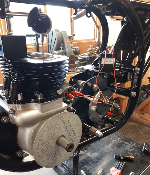 That has to be done with the automatic advance unit (AAU) tightened onto the magneto shaft. With the magneto secured, the AAU was released again. I had noticed that the AAU was a little reluctant to return to the fully retarded position. It was free enough mechanically, so I removed the two little springs for inspection. They were quite stretched and had little tension so I replaced them with a new pair that I had 'in stock' and that made all the difference. The AAU now returned to fully retarded as it should do.
Now comes the fun stuff. With a dial test indicator (DTI) set up on a magnetic base, attached to the top of the cylinder barrel, I set the engine to exactly top dead centre of the of the compression stroke on the left hand cylinder. Then a timing disc, basically a 360° protractor, was attached to the drive side crankshaft axle and a pointer attached under a screw on the crankcase. That was set to TDC (0°). I turned the engine backwards about 50° and then forward to exactly 32° before TDC. That's the point at which the magneto points should just begin to open with the AAU held in the fully advanced position. The 'accepted' way of determining when the points just opened was to use a sliver of cigarette paper between the points. I have a better method... A magic black box called 'A Magneto Static Timing Light' from The Magneto Guys. With this connected across the points, a red LED lights the instant the points open. The magneto armature could be rotated until the red LED illuminates, at which point, the AAU is tightened onto the magneto spindle. A quick check by rotating the engine backwards a little and then forwards again until the LED comes on, check where the pointer is on the timing disc and all's well. The magneto timing is correct at 32° BTDC (fully advanced) and I'm a happy chappie.
Monday, 16th February, 2024.
It was at this point that I started to think about the electrics, and more specifically, whether or not I should fit indicators. That's a bit of a 'no brainer' really if you intend riding in today's traffic conditions. So... having decided that I would, the next decisions were what type of indicators would I fit, and how would I fit them onto the bike. There are a lot of aftermarket indicators available. Some good, some not so good. In keeping with the age and style of the bike, I've decided to fit the Lucas indicators that Norton, BSA and Triumph fitted as standard, back in the day. They are big enough to be seen clearly in bright daylight, and shouldn't pose too much of a problem to fit. As always, when I fit indicators to bikes that didn't have them originally, I try to fit them in such a way that they can be removed, if a future owner doesn't want them, without too many problems and no lasting damage to the bike. The rear ones, I decided would be mounted on the sides of the number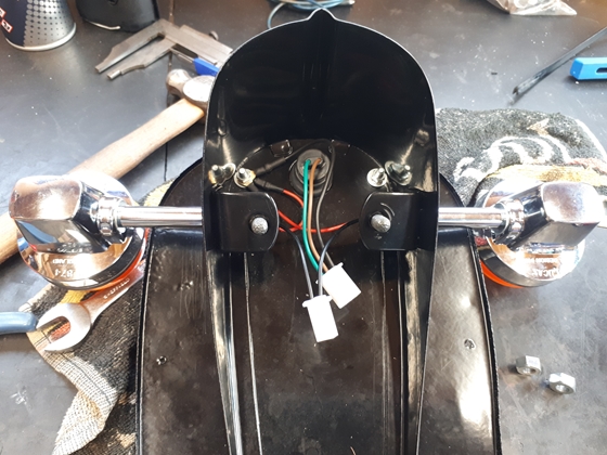
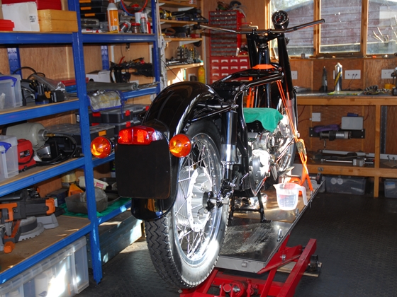 plate bracket. That would be convenient for two reasons. First, it just required two 7/16" diameter holes, which could easily blocked with a blind grommet if the indicators were removed at some future date. And second, all the wiring would go to the same place and between the number plate holder and the mudguard, there is plenty of room to make connections. On this restoration, I'm going to use the multi-pin type of connector block that are commonly fitted to modern bikes. The big advantage is that they use gold plated connection pins and sockets which give a good, reliable electrical connection and they are resistant to corrosion. As usual, the 'ground return' will be by a dedicated wire, directly back to the battery and I won't be using the frame or tinware as part of the electrical circuit.
The front indicators will be mounted either side of the headlight but just how they will be fixed remains to be seen. I'll know better when I've got the indicators and the headlamp shell comes back from the Lutton Body Shop.
Tuesday, 5th March, 2024.
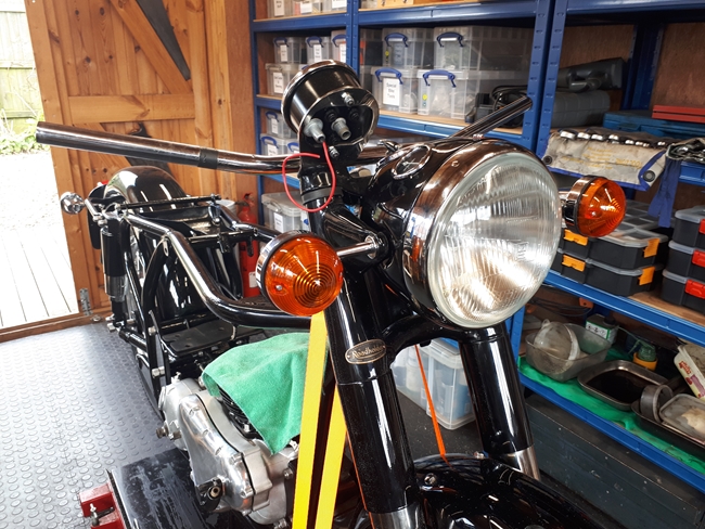 I picked up the last of the black paintwork from Kris at The Lutton Body Shop last week, and dropped off the petrol tank to be painted silver. Hopefully, that will be the last thing to be painted. As I've come to expect, the paint finish on the tool box, oil tank and headlamp shell was superb. Fixing the front indicators wasn't too difficult. It meant opening up the fixing holes in the headlamp shell and the fork shroud 'ears' to accommodate the 7/16" thread on the indicator stalks. The newly reconditioned speedometer and a new ammeter were dropped into the shell once it was in position. I had hoped to use the old light switch but on testing, it proved to be scrap. The internal contacts just weren't reliable enough so I had to 'bite the bullet' and buy a new one. I'd already got a new rim and H4 halogen headlamp unit, so after a bit of fiddling about, I got that fitted to the headlamp shell.
The oil tank was missing a couple of fixing studs. I did have a couple of old ones that would do, but I've ordered new ones 'cos that's the proper thing to do. At some point, I've got to think about the wiring and once I've got the toolbox fitted, I'll see what room I've got for a battery. Back in the day, this bike would have been fitted with two 6v lead/acid batteries connected in series to give 12v. These days, there's a bigger choice of 12v batteries and I'm sure I'll find one that will fit.
Tuesday, 12th March, 2024.
Well... that proved a little more difficult than I expected. The Norton battery clamping system, and the fact that it's located inside the tool box limits the size of the battery somewhat. Tayna Batteries eventually came up with one, a Powerline PTX7L-BS. It's a bit smaller than I'd hoped to fit, being only 7Ah, but I hope it will do. I will have to modify the clamp slightly by putting a little bend in it but that aside, I should be able to make it fit.
I've had second thoughts about the headlamp. The H4 halogen reflector unit didn't fit into the rim very well and with the "W" clips in place, I couldn't get the rim back onto the shell correctly. With that in mind, I've managed to source an original Lucas BPF reflector and I'm hoping that will fit better than the H4 unit. When it arrives in the next couple of days I'll find out.
Sunday, 31st March, 2024.
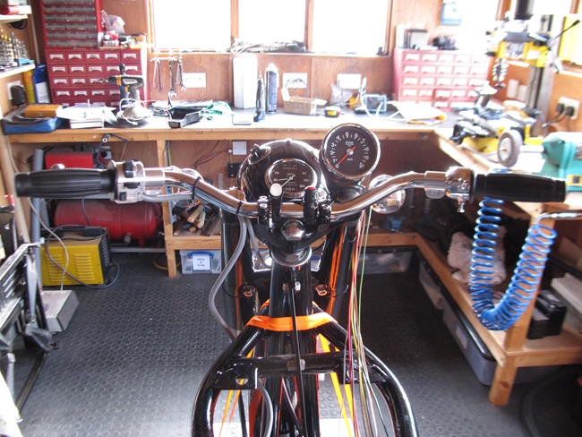 The BPF reflector unit arrived and fitted a lot better than the H4 unit. I've also managed to source a pair of relatively high power, 50w/40w, BPF bulbs from Amazon of all places!. Now that little problem has been resolved I could fit the switches onto the handle bars and start the wiring. Ahh... another slight problem. I had a spare "Norton Straight" handle bar that was originally on the Triumph T90, so I fitted that... and realised that the control cables from the clutch and brake levers couldn't be routed smoothly through the steering head. So... that handlebar came off and I fitted a classic British style with a slight rise. That would make the clutch and brake cable route much smoother. The switch cluster on the left hand side is a replica Lucas unit as fitted to the British bikes when indicators became a standard fitment. It houses the headlight dip switch, the indicator switch and the horn button. The magneto kill button is the red button in the centre of the handlebar. Also fitted there is the indicator warning light. That's "in your face" and bright enough that you won't inadvertently leave the indicators on after turning. The clutch and brake levers are cast alloy items from Venhill Engineering, the same as I fitted to the Bonneville. They look better and are better made than the chrome plated, replica "classic" levers available from most bike bit suppliers.
With that all sorted, I started to look at the wiring. I'm deviating a little from the wiring looms that I've made in the past in that I've decided to use "thin wall" cables. These, as the name suggests, are smaller diameter for the same current carrying capacity. I've spent a little time creating a wiring diagram. That way, I will know which wire goes where, and hopefully I won't make any silly mistakes... It has been known, surprisingly. I've started at the front end and will work backwards. For the moment, I've had to stop there as I realised that I needed some more 25A black cable. I'll continue when that arrives.
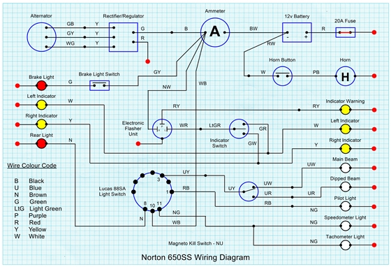
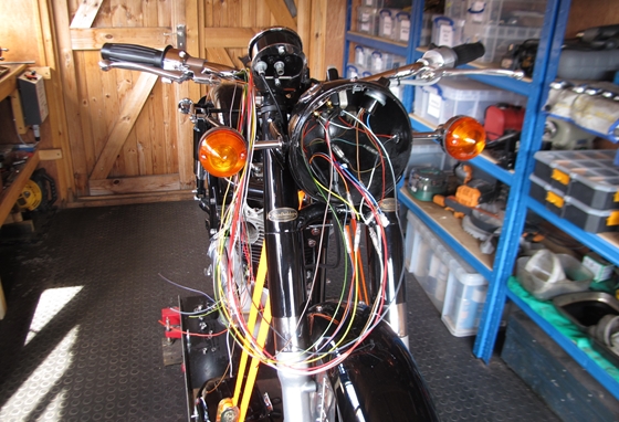
I've not actually been idle while I'm waiting for the cable to arrive. Thinking ahead for once, I know that I will be having to make new clutch and break cables. I'll use the Classic Bike clutch cable kit from Venhill as a starting point but I will have to solder on nipples. To spread the end of the inner Bowden cable, it's easier and more effective if you have what's called a "Birdcaging" tool. Venhill will supply one for the somewhat costly price of £159.04. I don't think so!! A couple of hours work and a couple of bits of steel from my scrap box and I have what I hope is a serviceable tool. I'll know if it works when I try it in due course.
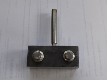
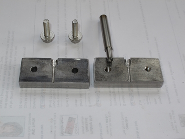
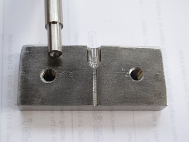
Monday, 8th April, 2024.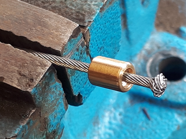
Well, I have to say that the "Birdcaging" tool worked better than I expected or could have hoped for. It put a beautiful "bird cage" in the end of the cable. When the inner Bowden cable was pulled down so that the bird cage was located in the end of the brass nipple and silver soldered in place, there is no way that the cable will be pulled out. Quite important, that, on a front brake cable!! That gives me confidence to do the clutch cable in the same way.
Thursday, 2nd May, 2024.
I have to admit, that I've not done a great deal to the Norton over the last little while. I have completed the wiring at the front of the bike but I was waiting for the petrol tank to come back from Kris at the Lutton Body Shop, so that I could determine the best route for the harness under the tank. I now have the tank back, and Kris has made a cracking job of it and it looks great. I did offer up the new badges and to be truthful, the fit wasn't great. Both will need some very careful adjustment to the curvature, particularly the right hand side. Not exactly sure how I'm going to accomplish that at the moment as the cast brass is likely to be a bit fragile. However... that's a problem for another day.
The mechanical side of things is currently being held up a little because the cylinder head is still with Pat Seager. Things need to be done in a certain order... I can't fit the primary drive until the side stand has been fitted. For that to happen, I need to have the left hand exhaust pipe in place as the stand needs adjusting to fold up out of the way, but not hit the exhaust pipe. The exhaust pipe, of course, needs the cylinder head to be in place. I do have the old 'racing' cylinder head, however, and for the moment that has been temporarily fitted. I've also had a bit of luck regarding the exhaust pipes. A posting I made on the Norton Owners Club forum resulted in a guy named Jon Newton contacting me and offering me a complete system that he'd taken off his own 650SS. I could have it free of charge and what's more... he would deliver it!! That arrived 4 days ago and is now on the floor in the workshop. Once the finned exhaust pipe rose nut that I've ordered arrives, I can fit the exhaust pipe and silencer. Then I can sort out the side stand and fit the primary drive.
Wednesday, 8th May, 2024.
We've progressed a bit in as much as the side stand has now been fitted to my satisfaction. With the second hand exhaust pipe fitted, the stand tucks up underneath it with plenty of clearance.
I've ordered a few small bits and pieces from Andover Norton. They will enable me to start assembling the primary drive. I have a new engine sprocket and chain. The clutch is complete, and I have the aluminium casting that the alternator stator mounts on. All I need to complete the job is the new 3 phase stator. I'll order that soon.
OK... on a completely different tack, I've been in touch with Paul Watkins, one of the "Records Officers" at the Norton Owners Club. I will, in due course, be needing his help with acquiring a new registration. The frame number is corroded (see photo in the 7th July 2023 blog entry) but it is readable(ish) if you know what the number is, but needs it be a bit better for the DVLA. Enter Mr Watkins... Before retiring from the Police Force, he was a qualified vehicle examiner, mainly looking at vehicles involved in fatal accidents. Later he specialised in the identification of cloned vehicles. He has the knowledge and skill to forensically enhance engine and chassis numbers. In the fullness of time, he will come to see the bike, work his magic and write a report that will be accepted by the DVLA... I hope!!
Saturday, 22nd June, 2024.
Dearest Gentle Reader... Lady Whistledown has returned. Much has happened in the 'Ton' whilst I've been away. Not the least of which has been me, watching far too much "Bridgerton". However, some progress has been made to the Norton and also a setback or two. I'll deal with the setbacks first. Before assembling the primary drive, it seemed sensible to offer up the new rear chain. It was too long, but I knew that when I bought it. Before shortening it, I wanted to move the rear wheel forward as far as it would go. However, the new adjusting screws were either too long or the threaded hole on the rear fork was jammed with crud... so I screwed in a 1/4" x 26 t.p.i. plug tap... and snapped it off in the fork. I uttered that immortal phrase "Oh Dear", well something like that, anyway. There was no way I was going to get the broken tap out with the tools and equipment I had to hand. I removed the rear wheel, unbolted the rear shocks and took the rear fork out of the frame. A phone call to Barry at T & L Engineering confirmed what I'd hoped... He would get the broken tap out for me; and he has. So the rear fork is now back in the framed and we're pretty much back to square one. The next task was to reassemble the drive train... primary chain, clutch and final drive. That's where the next 'setback' reared it's ugly head. With the clutch securing nut fully tightened to the specified 70 lb/ft torque, the gearbox was pretty much jammed solid. slackening the nut released the gearbox and it turned freely again. It wasn't anything I'd done, specifically, other that build up the AMC clutch from a lot of assorted parts that came in one of the various boxes of bits. It appeared that the splined 'spider' in the clutch hub was just a few thou too long and was binding on the end of the output gear sleeve. Putting it up in the lathe and removing 0.010" at a time until it could be fully tightened and not jam cured the problem.
Now the better news... Pat Seager phoned a couple of days ago to say that the cylinder head was ready for collection, so yesterday, I drove down to deepest Suffolk and picked it up. I have to say that he's made a terrific job of it and I'm well pleased. That means that I can now get on with the rebuild. The only problem being that it's now 'festival season' and I will be spending a lot more time with Christine so my time in the workshop will be severely limited.
Friday, 27th September, 2024.
It's been an eventful few weeks. The Norton was rolled out of the workshop to be replaced by first, the Matchless G80CS and secondly, the Triumph Bonneville as they both needed my attention. With the work on the Triumph now completed, I could finally get back to the Norton. First job was to assemble the rockers into the cylinder head. That was easy enough but I was disappointed with the result. OK... I know the geometry of the Dominator's valve gear has been criticised and had been changed by the factory over the years it was produced, but I wasn't expecting it to be quite as bad as was on my cylinder head.


The rockers were assmbled as per the instructions in the workshop manual, with the thin steel shim washer at the outer end of the rocker and the "Thackery" spring washer at the inner end to take up the end float and push the rocker to it's outer limit. As can be seen in the photos above, only one of the exhaust rockers had the clearance adjusting screw even remotely on the same centre line as the valve stem. That might have been good enough for Norton, back in the day, but it wasn't acceptable to me. I never did like those Thackery washers... Always thought they were a bit of a 'bodge' to make up for bad machining and they increase the friction in the valve train. I'm going to 'do away' with them and do what the café racers did back in the '60s, namely to machine up custom brass spacers for each end of the rocker to bring them into line with the valves and also reduce the friction. I will put a steel shim washer at each end, against the cylinder head to stop the aluminium wearing against the brass spacer.


There... all done. Now I'm happy!! The photos distort it a little, but I can assure you that the clearance adjusting screws are, as near as makes no difference, on the valve centre line.
Wednesday, 9th October, 2024.
 OK... with the head rebuilt to my satisfaction, and the workbench empty, it was time to bring the Norton back in from the cold. I have a set of Wassell after-market solid aluminium pushrods but the general consensus on the Norton forum was that I'd be better off not using them as they wear quickly. Bearing in mind that I was building this bike up from a lot of miss-matched parts, I wanted to know if the pushrods were at least the right length. To change the rocker geometry, Norton increased the length of the valve stem by 0.1" and reduced the length of the pushrods by the same amount. The Wassell items were the longer, pre-change, version. My intention was to assemble the head to the engine with those pushrods and check that I could correctly set the valve clearances. Any miss-match would be obvious. What a palaver that turned out to be. Trying to fit the head whilst holding the four pushrods in position was bloody near impossible!! I managed it in the end with the aid of a small torch and a piece of stiff wire bent into a hook. With that, I could just about get the pushrods located onto the rockers. As it turned out, those pushrods are the correct length, so I've ordered a set of new pushrods with steel ends from Andover Norton and will go through the whole damn thing again when they arrive!
The Norton had been relegated to my smaller workshop while I carried out some maintenance on the Bonneville and the G80CS. During that time I had noticed a small puddle of oil on the floor. As the only thing with oil in was the gearbox, it had to be leaking from there. With the bike up on the workbench, it was obvious that the oil was leaking out of the front cover, from around the kickstart spindle. Now that was annoying as I'd deliberately fitted the later, supposedly better, "X-ring" oil seal to the outer cover when I rebuilt the gearbox. I don't remember the kickstart spindle being worn or damaged, though. I've taken the outer cover off and checked the spindle. That's perfectly OK, there's no sign of any wear or damage to the area that the seal locates on. I removed the X-ring from the outer cover and tried it on the spindle. To my mind it was much too loose and slid easily along the spindle. I'm not surprised that the relatively low viscosity gearbox oil was weeping past it.  Hmmm.... I'm not unfamiliar with o-ring seals and there uses as I used them frequently in my working life as an engineer. Bearing in mind that the only time there is any relative movement between the O-ring and the spindle is when you are actually kick-starting the machine, the O-ring has a pretty easy life, it just needs to keep the oil inside the gearbox. I measured the width of the seal location in the cover... 4.5mm... the X-ring was only 3.5 mm wide, so no sideways compression and no pressure differential between the inside of the gearbox and the outside world to keep the seal pressed against one side, either, then. No wonder it was leaking. I looked around for a suitable replacement and found what I was looking for from Simply Bearings Ltd. A Viton O-ring, 4mm cross section, 25mm I.D. That would fit the groove nicely and give a little radial compression on the 1" diameter kickstart spindle. The Viton material would be better suited to being submerged in oil than the cheaper Nitrile material, so a better proposition all round. It took a little effort to get the cover back over the kickstart spindle, but it did go on and I'm much happier now. The gearbox was topped up with a pint of straight SAE40 mineral oil. Time will tell if I've cured the leak.
Thursday, 10th October, 2024.
 The new pushrods arrived this morning so it was time to fit the cylinder head... or so I thought! Having had a bit of practise earlier, it only took about 20 minutes to get the head in position and the pushrods located! There are five bolts, four long and one short that secure the head to the barrel. They are relatively easy to fit and indeed, the stainless items sourced from Andover Norton all fitted perfectly. It was three of the other five fittings that gave me trouble. Apart from the five bolts already mentioned, there are two, 5/16" dimeter studs screwed into the cylinder barrel at the front. The head fits over these and is secured with nuts and washers from above. They also were fine. The final three fixings are all 3/8" diameter studs, screwed into the head. They locate through holes in the cylinder barrel and are secured with nuts from below; 2 sleeve nuts at the front and a normal hex nut at the rear. With hindsight, I should have checked that the nuts actually fitted the studs before fitting the head. I didn't and they didn't. The nuts only went on about 3 or 4 turns than jammed. When I tried to undo them, the studs unscrewed from the cylinder head with the nuts still jammed on them. That meant that the head had to come off again... buggeration and fuckery!!!
When I got it all apart again, it was obvious that the threads were correct (26 t.p.i.) but either the studs were oversize or the thread in the nuts was undersize. I could sort that as I had both 26 t.p.i taps and a die. A plug tap was run into the nuts and removed a small amount of material. The studs, I put up in the lathe and ran the die down them. That also removed a small amount of material. The nuts now fitted the studs perfectly. Hooray... Then I noticed that the 3/8" B.S.F. thread on the other end of one of the studs needed cleaning up as I had distorted it a little getting the jammed nut off. Trouble is, I didn't have a 3/8" B.S.F. die. I have one on order from Tracy Tools Ltd and will hopefully complete the task in the not-too-distant future.
Saturday, 12th October, 2024.
 The 3/8" B.S.F. die arrived yesterday so the damaged thread on one of the studs has been repaired. I've taken the decision to screw these into the head using a little Loctite 243. That may stop the studs unscrewing with the nuts, should it all have to come apart at some point in the future. That was done yesterday and the head left overnight so that the Loctite could cure completely.
This morning, the head was finally installed onto the cylinder. The bolts were tightened to the torque specified in the workshop manual. The valve clearances were set, 0.006" for the inlets and 0.008" for the exhaust. With valve covers in place, the head steady was fitted and the horn attached to the head steady. The last thing I did today was to fit the carburettor mounting studs and the two aluminium spacers that I repaired some time ago. One final observation, there is no sign of any oil leaking from the gearbox, so it would appear that problem has been solved.
Sunday, 27th October, 2024.
 A little more has been accomplished but it's still slow going. The oil tank and battery box have finally been fitted. A new set of rocker oil feed pipes has been made and that has also been installed. The wiring harness from the front of the bike has been routed along the left hand frame tube and cable tied in place. That will be routed into what was the tool tray and is now where all the cable connections will be made. The MOSFET rectifier / regulator has been attached to the underside of the tool tray, where it will be in the airflow to keep it cool.
I discovered that the alternator rotor that I'd hoped to used was, in fact, faulty. The main body of the rotor was loose on the steel bush in the centre. That meant that I've had to source a new one; another expense I hadn't planned on. The alloy carburettor castings will be sent off to Simon at Bike-Aquablasting to be cleaned up. They've been de-greased in the parts washer and then in the ultrasonic tank but they still looked old and somewhat corroded. Vapour blasting will bring them up like new, hopefully.
Tuesday, 5th November, 2024.
The new rotor arrived a few days ago and has been secured on the end of the crankshaft. The 12v, 3 phase stator has also been fitted. That wasn't without it's own problems. The stator is held in place with three, 1/4" studs. The Haynes manual, the NOC Dominator Service Notes and Roy Bacon's Restoration guide all quote 15 lbs/ft as the correct torque for the nuts on these studs... DON'T TRY IT!! The nuts/studs will strip long before you reach that figure, and reading the forum posts, I'm not the only one to discover that. I don't know where that figure came from originally, but it seems that it's been copied into all the reference works and treated as 'gospel' without it being checked. Forget the torque wrench and use your experience and 'feel' when you tighten them. Gripe over! The stator output cable has been secured with a couple of cable ties. That will keep the cable away from the primary chain.


The wiring has been completed and guess what? It all seems to work. As mentioned above, somewhere, I've utilised the tool tray to make all the connections in. The rectifier/regulator had been bolted underneath and the brass studs I used for that have served as the connection for all the red earth return wires. The electronic flasher unit is attached to the rear of the tray.
Just one last thing to add at this point. The dual seat has been parcelled up and sent off to Andrew at R.K. Leighton for a complete restoration. Having exchanged emails, he tells me that the turn around is about three weeks.
Sunday, 17th November, 2024.
The carburettors have come back from "Aquablasting" and look a lot better than they did when I sent them away. I've given them a thorough cleaning and ensured that there are no tiny glass beads where they shouldn't be. I offered them up to the cylinder head and immediately found the first problem. There was no way I could get a spanner onto the two nuts in the middle, between the two carburettor bodies. Ok, I'm fitting two Mk1 AMAL Concentrics where it originally had a pair of AMAL Monobloc carbs, one without the float chamber. Maybe there was more clearance with that set up.


I pondered over the problem for some time before coming to the conclusion that the only way forward would be to modify the carb bodies slightly to give clearance for a small socket spanner (also modified with a reduced outside diameter). This I have done, but I'm guessing that some people will be horrified. New control cables for the throttle and air slides are on their way but if past experience is anything to go by, I'll probably have to modify them, one way or another.
Thursday, 28th November, 2024.
The throttle cables arrived and as expected, they needed to be modified slightly. The inner cable was too short, or conversely, the outer sheath was too long. It needed to be shortened by about 5/8". That's quite a delicate operation as you have to cut the spiral steel 'tube' without damaging the inner cable. I managed that, as I've done before, with a fine cutting disc in the Dremel. Both cables have threaded adjusters so that they can be individually adjusted to take up any slack, once the engine is running and the carburettors have been set up for a correct 'tick-over'.
As it happened, the air slide cable fitted without any need for modification. This cable has a junction 'splitter', where the single cable coming from the control lever is split into two cables, one to each of the carburettors. As I've found out before, that splitter doesn't have enough movement to cover the full range of the carburettor air slide. You can set them so that the slides close fully, but don't fully open or so that they open fully, but don't fully close. Not a good scenario, but without resorting to making my own, longer splitter junction box, there is no option. On my Bonneville, I've removed the air slides completely as they aren't really necessary, the starting mixture can be richened by flooding the float chamber. With that in mind, I've set the air slides on the Norton to open fully, but in truth, they will probably never be used... by me, at least.
One last thing at this point... This morning I received an email from Andrew at R K Leighton to say that my seat is ready for despatch. I've transferred the required lump of wedge via a BACS payment and expect delivery of the reconditioned seat sometime next week.
Monday, 2nd December, 2024.
The last few day have been frustrating, to say the least. It seems to have been one step forward, three steps back. I have to take some of the blame. Putting a bike together that you never took apart in the first place is bound to throw up a few curved balls. It was time to offer up the petrol tank with a view to sorting out the petrol feed pipe to the carburettors. That's when I hit the first problem. The air slide cable splitter junction box was very definitely in the wrong place and was stopping the tank from sitting on it's front mounting rubbers. I pondered, pushed and pulled. The cable was just plain wrong. The two cables to the carbs were too long and the cable to the control lever was too short. In the end I gave up and stripped the whole lot off. The Bonnie runs fine without air slides, the Norton will too. The cable holes in the mixing chamber top covers were blocked off with 1/4" diameter steel balls and a touch of silicone sealant to stop any air leaking in and upsetting the mixture.
With that little problem out of the way, and the tank correctly located, it was time to look at fitting the petrol tap to the tank and making up the fuel pipes. That's when the second problem arose. The tank only has one fuel outlet at the rear of the tank on the left hand side and it's very close to the top frame tube. Ho hum... When I made up the wiring harness, I'd run it very neatly along the top frame tube... on the left hand side. It was very neatly stopping me fitting the petrol tap. Off came the tank again and the harness re-routed. Third problem. I still couldn't fit the petrol tap with the tank located as it fouled the top, left frame tube. Looking at it, it wouldn't work in that position anyway. If I fitted the tap first and then dropped the tank into position, I still wouldn't be able to operate the tap as it would be obscured by the aforementioned top frame tube. It needed some sort of adaptor to bring the tap below the frame tube.


A shoogle in my scrap box came up with a suitable piece of CZ121 brass that would do nicely. A short while later I had my adaptor, fitted the fuel filter that came with the petrol tap and the assembly offered up to the tank. I've used bonded rubber "Dowty" seals in the appropriate places. With a little care, I could just about wiggle the tank into position on the frame with the tap assembly in situ. That must rate as a "result". After that, making up the petrol pipes was a piece of cake, and was accomplished without drama.


OK... with the tank now located, I could think about the tank badges. As mentioned back up the page about 18 months, I sourced a pair of replica badges from Donald Pender in America. These had been cast in brass, polished and chrome plated. They looked better that the original badges but the curvature was slightly out and would need 'adjusting'. I have the tool for that!! A little pressure applied in roughly the right place and after a couple of attempts, I've got them to fit the tank to my satisfaction. I've not fitted them yet as I have a little job to do on them first.
Friday, 13th December, 2024.
That little job has now been completed. The roughly rectangular area that the word "Norton" occupies needed to be painted black so that the name stood out. I know that my unsteady hand and lack of artistic skills precluded me from doing it by hand with a fine brush, so I came up with another solution.


I masked off the offending area and sprayed the whole lot gloss black. Then, with a strip of kitchen towel wrapped around a small wooden block and moistened with acetone, I wiped most of the paint off the top of the letters. I finished off with an acetone moistened cotton bud (Q-Tip) to clean off any remaining paint. I was quite pleased with the result! They were left overnight and then attached to the tank with new, stainless screws. 
There are small, moulded rubbed knee grips that cover the rear of the tank badges and two of the screws. These were trimmed slightly to fit and attached with high strength "3M 468MP" double sided adhesive. They won't be falling off anytime soon!.
The seat came back from R K Leighton a few days ago. They have done their usual terrific job of refurbishing it. They'd even fitted new mounting rubbers. A little red rubber grease on the frame pins at the front and the seat slipped easily into place. It was secured with a new DZUS Fastener at the back. I think the light at the end of the tunnel is actually daylight now, and not just another train coming...
Wednesday, 12th February, 2025.
Hmmm.... It's about two years since I started this "little project", and hopefully, it's not too far from completion. I've done nothing since the middle of December, at least... nothing of note regarding the Norton. I have repaired the wheel hubs and axles on three monster trucks, but that's another story!! Christmas and New Year have come and gone, Winter hasn't really got started in rural Lincolnshire, so it's about time I got to grips with the 650SS again. I've bought an exhaust system, two pipes and two silencers, from the Norton Owners Club as they had them is stock and they were competitively priced. I'd been a bit concerned about the run of the tachometer cable and it's proximity to the right hand exhaust pipe. I didn't like the way the drive gearbox on the timing cover directed the cable straight into the pipe. Having fitted the right hand exhaust pipe, I was right to be concerned about the tacho cable. It isn't good. OK... it's fitted with a coiled wire heat shield but what a stupid design. That will have to be changed somehow.


I've since unpacked the right hand silencer and I have to say that I'm disappointed with the quality of the chrome plating. The chrome appears to have been just flash plated onto unpolished raw steel. There is no evidence of copper or nickel plating prior to being chromed. The surface is extremely rough, not the smooth polished surface you expect from chrome plating, and there are pinprick holes already showing rust in one place. These will not be used and will be returned to the NOC for a refund. I'll source a pair from elsewhere in due course. The pipes, on the other hand fit well and the chrome plating seems to be satisfactory, so I'll keep those.
Thursday, 6th March, 2025.
The defective silencers were indeed returned and a refund issued... Thank you NOC. I've not ordered any replacements yet, I'll do that in a couple of weeks as I'm off for a weeks fishing next week and they'd be nobody here to receive them. Right... back to the problem with the tachometer cable. I've made an adaptor plate out of 4mm thick stainless steel. That orientates the drive gearbox correctly. I've made a similar thickness spacer to go behind the slotted drive nut on the end of the camshaft, that ensures that there is the same drive engagement. There was plenty of thread on the end of the camshaft, but I might just use a little blue Loctite when I put it together finally.


Thursday, 20th March, 2025.
I ordered a pair of silencers from Armour Motor Products a few days ago and they arrived yesterday. The chrome is so much better than ones I bought from the NOC. The timing side is now almost finished, a new crankshaft oil seal and oil pump sealing rubber washer fitted and the timing cover now screwed back in place. The right hand exhaust pipe and silencer are now in place, as is the tachometer drive gearbox and cable. Notice the very smart custom made (and expensive) stainless steel exhaust pipe ring nuts. These were supplied by Seager Engineering, along with a matching tightening tool.
Tuesday, 9th April, 2025.
Just a quick update to say that the bike is now virtually finished. It needs a kickstart lever, which is on order but not yet arrived, and the battery box cover fitting, which I have and will fit when I'm sure that I won't need access to the battery again... That's it Finito. I'll be back in touch with Paul Watkins, the Norton Owners Club Dating Officer, in due course as I will need his expertise (to say nothing of a Certificate of Authenticity) to enable me to get a registration. Hooray... Maybe I'll get to ride it before too long. (Photos will follow once it's been wheeled out of the workshop.)


The day has finally arrived. I've run out of excuses not to try and start the bike. I poured in a gallon or so of petrol, tightened up a couple of connections and gave her a kick. It fired, but didn't run. It was on the 5th or 6th kick that she actually burst into life. The engine is still very tight, so I didn't run it for too long. Just long enough to let me know that I was in the right ball park with the settings. The carburettors will need some adjustment but that I can do when she has a few miles on the clock and has loosened up a bit. I'm a happy bunny!!!
Monday, 11th August, 2025.
However.... There's always a "however". One thing that had slipped my failing memory was the side stand. It was tucked neatly up under the nearside exhaust pipe, but there was no way I could put it down with my foot. Like the centre stand, it needed a short extension. That was tackled this morning. A length of 1/4" steel bar was bent to fit and sif-bronze brazed to the foot. Not my neatest bit of brazing, but it's not going to fall off any day soon, so it will do nicely!!


Thursday, 4th September, 2025.
Paul Watkins, from the Norton Owners Club, phoned me a couple of days ago. Having finished his racing commitments, he was now free to come over and have a look at the bike's frame number. Dates were discussed and he will be coming over next Wednesday, 10th September. Only one slight hitch... We would like to be able to lay the bike down on it's right side in order to apply the chemicals needed to the frame. In the meantime, I'll remove the exhaust system on that side and arrange some pillows/cushions/whatever to protect the bike. He's bringing another guy with him so with three of us, it shouldn't be too stressful... hopefully!!!
Thursday, 11th September, 2025.
As promised, Paul Watkins turned up with his colleague, Kevin, around lunchtime yesterday. We had a look round the bike, then wheeled it out into the garden. With suitable padding in place we laid it down a little way onto it's right side so that Paul could work on the frame number. To be honest, it didn't work as well as expected. Paul ground so much metal away in an attempt to get below the pitting that he'd possibly gone past the point where a number could be recovered. Ho hum.... He was, however confident that the DVLA would accept his findings, and would issue an age related number. The frame number was also backed up by the "Reynolds Number". "What's that?", I hear you ask because I had to ask too. Well it's a number that's stamped into the head steady support bracket behind the steering head stock on the frame. It is stamped on when the frame is put together and indicated the month and year that the frame was built. Once the powder coating had been cleaned off, the stamping showed up as " 1 | 63 | M " indicating that it was built in the 1st month (January) of 1963. That correlates well with the conclusion that Paul came to, from looking at the factory record, that the bike was despatched from the factory between the 5th and 11th of May of 1963. So... I've applied for an official dating document (NOC2) from the Norton Owners Club, which Paul will prepare in due course. With that, I can apply to the DVLA for a registration.


Friday, 26th September, 2025.
The document that Paul Watkins produced arrive a few days ago. That, along with a DVLA V55/5 form duly completed, the photographs asked for, the documents needed to confirm my name and address and a cheque for £55.00, were posted off to the DVLA on Monday. I don't expect to hear anything for a week or two but I feel a lot more confident, having seen Paul's very professional work, that an age related registration number will be issued in due course. I've uploaded a PDF scan of Paul's document, and if you're remotely interested, it can be viewed via the link at the bottom of the page, or by clicking HERE.
Tuesday, 7th October, 2025.
Hooray.... Those very nice guys at the DVLA have accepted my application and this morning, a new V5C document arrived. I have an "Age Related" registration ... 'DRS 814 A'
A quick call to those equally nice people at RH Specialist Vehicle Insurance and the Norton was added to the ever growing list of bikes on my classic insurance policy... That's seven now. The cost, just £16.80.
Just checked on the GOV website and it's showing that the Norton is taxed until 30th September 2026. That is a result.
Tuesday, 14th October, 2025.
Typical... I've not even ridden the bike yet and I'm about to change one of the major components, namely the front brake. I've been looking, half heartedly I'll admit, for a twin leading shoe front brake. Good second hand items, like the one John Tickle used to market, are few and far between. Andover Norton do one but that's over four hundred of our fine British quids. So... I was browsing one of the many Norton related FaceBook pages when I spotted a post from Don Pender... Remember him? He's the American gentleman who supplied me with a pair of his very nice custom made petrol tank badges. It would appear that, among other things, he also produces an equally nice TLS brake plate assembly. A couple of emails exchanged and one of his assemblies will very shortly be winging it's way over the Atlantic to me. The price, including DHL delivery, a reasonable $395 or £310 if you need it that way.
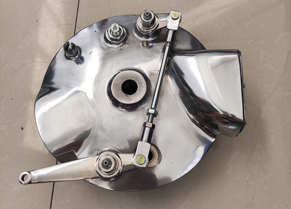
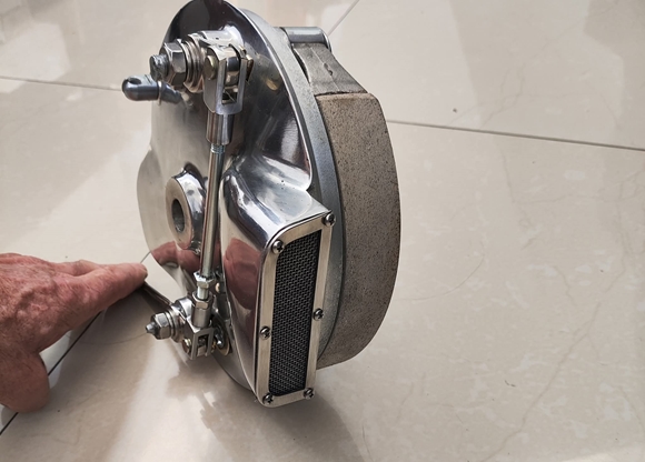
Friday, 24th October, 2025.
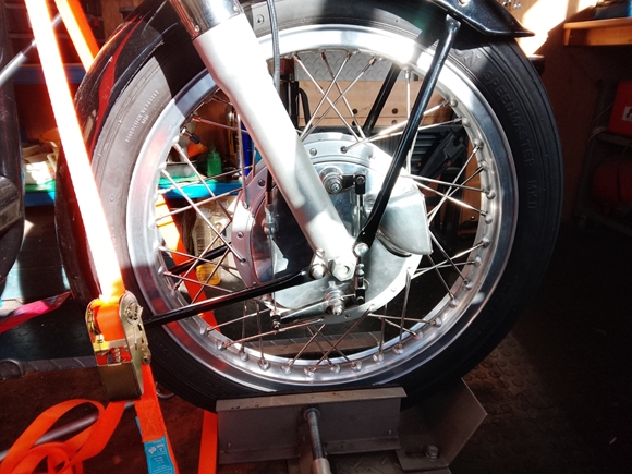 The new TLS front brake plate assembly arrived a few days ago, and very nice it is, too. I dropped the front wheel out and removed the SLS brake. I wanted to see how accurately the new plate had been set up, so I chalked both shoes, fitted the brake plate and spindle, then rotated the brake plate with the brake applied. It turned out that the brake had been set up perfectly. The chalk had been rubbed off both the shoes by the same amount at the leading ends of the shoes. I was happy with that so the wheel was refitted to the forks.
I had to make up a new cable so as I usually do, that was made up from a Venhill kit, using the 8mm heavy duty option. The brake will need to "bed in" but I fully expect it to be well up the the bikes performance.
Monday, 30th March, 2026.
Well, it's finally happened... My restored 1963 Norton 650SS has made her maiden 'voyage'. Not a long one, just a 5 mile run 'around the block', but it was long enough to let me know that we're almost there.  The carburation need tweaking a little but that we can do. There was a rubbing noise coming from the front brake. I think the TLS brake plate assembly that I sourced from Don Pender in the States is just rubbing on the edge of the brake drum. That's easily sorted, too. Apart from that, all seems well. There are no obvious oil leaks and the oil IS circulating. All in all, I'm a happy bunny. It's been a long journey from the trailer load of bits I bought from Ted to what you see in the photo. Close to three years and a not inconsiderable chunk of wedge. I hadn't intended it to take that long but sometimes Life, the Universe and Everything just gets in the way.
Tuesday, 31st March, 2026.
With the Norton back in the workshop, it was time to address the front brake plate issue. As suspected the edge of the new TLS brake plate was just touching the outside edge of the brake drum. I suppose I could have just put it back and let it wear itself down but that didn't seem right. Unfortunately, my lathe isn't big enough to mount the brake plate so that I could turn a few thou off, so I opted to shim the brake plate out a little.
The front wheel axle is 17mm diameter and those very nice people at ACCU LTD do a range of stainless steel shim washers with a 17mm I/D and a 24mm O/D... Perfect!! I placed an order late yesterday afternoon and they were delivered by DPD this morning. I selected one 0.3mm (.012") thick and slipped it onto the axle between the wheel bearing and the brake plate. With the wheel back in the forks and the axle nut tightened to the specified torque (60lb-ft), the wheel spun freely with no rubbing. Splendid... the job's a good 'un.
The carburation was a bit more guesswork. The engine was "hunting" a bit at tick-over, which would indicate that the mixture was a bit lean. I simply screwed the pilot air screw in half a turn on each side. Well see if that has made any difference when I start her next time.
Link to Index and Home Page.
Link To the NOC document from Paul Watkins.
Link to AJS M18S page.
Link to Matchless G3/LS page.
Link to Triump T120R Bonneville page.
Link to Triumph Tiger 90 page.
Link to Matchless G80CS page.
Link to Honda VFR750 page.
Last updated 31/03/2026