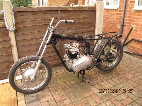
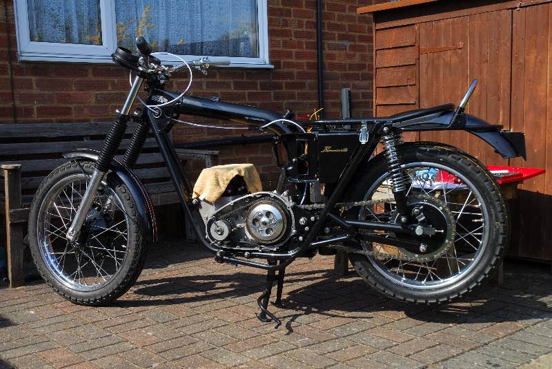
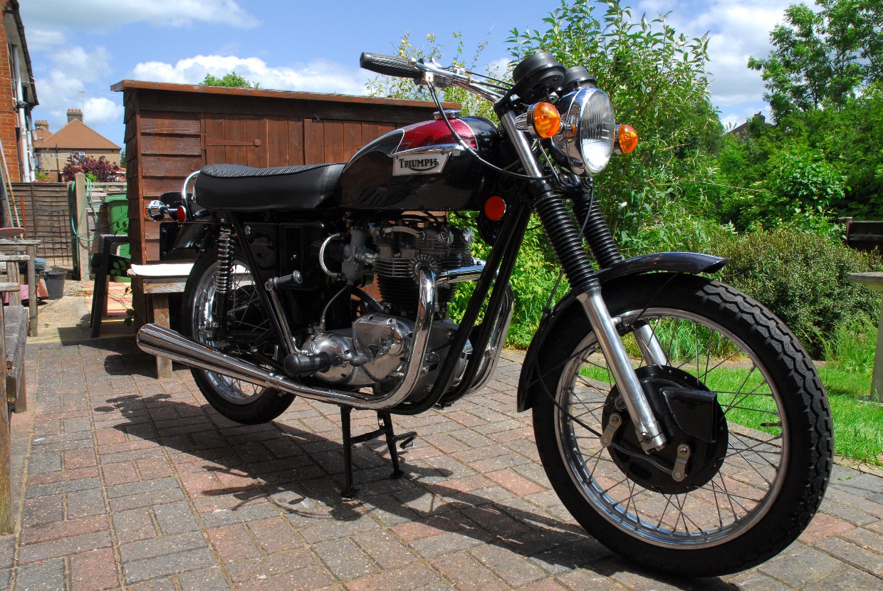
 The plan was to ride it for a while then strip it down for a complete rebuild towards the end of summer 2014. That got delayed a bit as I'd also bought a 1980 Moto Guzzi Le Mans (the red and black machine, another 'spur of the moment' purchase) that needed some work to make it rideable and road legal. That work is now finished and I can finally start work on the Bonneville. I put quite a few miles on it during the summer. It actually ran extremely well and proved very reliable, with one exception. The final drive oil seal in the gearbox leaked very badly if the bike was left parked on the side stand. That will certainly need replacing. The bike had already been 'up-graded' in some respects by the previous owner. The standard alternator, selenium plate rectifier and zener diode regulator had been replaced with a 180 watt, 3 phase alternator and a solid state 'Podtronics' integrated rectifier/regulator. He had also fitted a Boyer electronic ignition system in place of the old contact breaker set-up. A 'Norman Hyde' seven plate clutch has replaced the original six plate setup. Oh, yes... A halogen headlight and relays replace the original glow-worm that Triumph fitted. Electrical wiring doesn't seem to have been the previous owners forte, however. There are quite a few 'loose ends' and probably a couple of reels worth of pvc insulation tape lurking under the saddle. That will all be sorted in due course as I'll make up a new custom wiring harness.
Over the last year, I've been 'collecting' stuff that I know I'm going to need or replace. Stuff like gaskets and oil seals, of course, but also more 'exotic' stuff. From America, I sourced a hydraulic clutch kit to replace the standard cable operated system and a state of the art optical 'PowerArc C5' ignition system to replace the outdated Boyer bits. They were not cheap!! I've also been collecting stainless steel fasteners and fittings to replace the rusty nuts and bolts. So... time to start.
20th November, 2014
The bike is now under cover at home and today I started to take it apart. The seat came off first. The cover is split and the front hinge has rusted and broken away from the seat pan so I'll replace the whole thing. 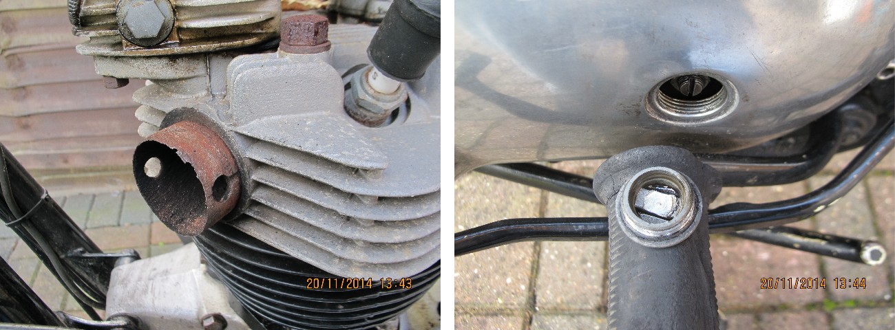 It will probably be cheaper than getting the pan welded up and re-upholstering it. The petrol tank was removed and drained next. The battery looks fairly new and is a good quality Bosch item so that's now connected up to my Oxford maintenance charger that will keep it in good condition until I need it again. The exhaust system proved a bit stubborn but a squirt of WD40 and a rubber mallet persuaded it to part company with the engine. The steel exhaust stubs looks a bit worse for wear. They may be ok or I may replace them... I'll wait and see. That's pretty much all I did today. I did notice a couple of things, though. First, the bolt securing the cylinder head steady to the frame is missing. Presumably it vibrated loose and fell out at sometime in the past. Also, the clutch adjustment needs looking at. The adjusting screw has been contacting the inside of the inspection cap and has 'milled' it's way into the aluminium. That will get corrected when I install the new hydraulic system.
24th November 2014
Today the sun was shining brightly and it was surprisingly mild for this time of year. A good day to take a few more bits and pieces off the Bonneville. I started with the rear brake pedal, connecting rod and rear brake arm trunnion. 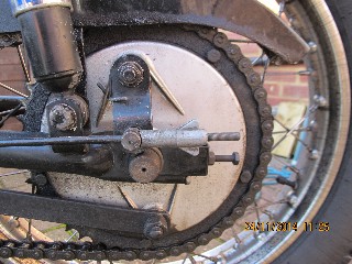 For future reference, the connecting rod is 1/4" diameter, 19.3/8" long and has a 28 t.p.i. thread for the adjusting screw (which would make the thread 1/4" UNF). While I was working in that area, I also removed the rear brake light switch, which is broken and will need replacing, both rear engine mounting plates and the footrests. The final drive chain was also removed.
 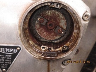 The clutch cable, tachometer drive cable and speedometer drive cable came off next. The speedometer had stopped working the last time I rode the bike and I thought the inner cable had probably broken or the square on the end had rounded off. This proved not to be the case, however, as the inner cable is intact but does not turn when the rear wheel is rotated... bummer... That would indicate that it's the rear wheel drive gearbox that's at fault. Something else I may have to source for the rebuild.
The side panels and air filter boxes were the next items to be removed giving better access to the carburettors. At this point I disconnected and removed the two throttle cables and the air/choke cable assembly. The two carburettors were then removed from the engine to make it a little easier to get the engine out of the frame when the time comes. The plastic insulation tape covering the alternator cable connections was removed and the alternator disconnected from the rectifier/regulator unit. There are three wires from the alternator... green/black, green/yellow and white/green. They were connected to the three yellow cables from the rectifier/regulator. The oil pressure switch was disconnected (a white/brown wire) and the HT leads and plug caps removed.
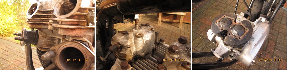
At this point I stopped for a coffee while the oil was draining from the oil tank (main frame tube). Only one more job to do today and that's to disconnect the Boyer ignition pick-up assembly. I removed the cover.... yuk!! It looks like the oil seal hasn't been doing it's job properly and it's a right mess in there. It's a good job the whole shooting match is being replaced. As it is being replaced, the wires were just cut as I can't get the cable out until the timing cover is removed.
27th November, 2014
It's dry again today and I have time to remove a few more bits and pieces from the chassis. First off, the gearbox was drained... Not that there was a lot of oil left in it as I'd stupidly left the bike on the side stand in the garage and most of the oil was on the garage floor having leaked out through the faulty oil seal mentioned earlier. 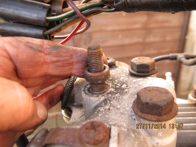 Ho hum... The primary drive case was also drained but there wasn't much in there either. What there was at least looked like oil and wasn't contaminated with water so it looks like the breather system is doing it's job correctly. Having done the messy stuff, it was just a case of unbolting the various bits and pieces that go to making up a motorcycle. The side stand and spring were first followed by the final drive chain guard and the engine breather pipe that's clipped to the rear mudguard. The pipe clips are very rusty and one was missing completely. They will be replaced in due course. The electrics under the seat were tackled next. They look a bit of a mess but that will also be sorted later. As the electrical system had been modified from the original Triumph layout, the original wiring harness isn't really of much use any more. It will be easier for me to make up a completely new harness when the time comes.
Once the wiring odds and ends were removed it was simply a case of unbolting the tool tray, the coil carrier plate and the battery carrier. The 'Podtronics' rectifier/regulator unit was bolted to the underside of the battery carrier. The chassis is looking a little bare now. The last job I did today was to remove the cylinder head steady in preparation for removing the rocker boxes prior to lifting the engine out. I noticed that the steel spacers fitted between the rocker boxes and the head steady had crushed down into the softer aluminium casting. That may make removing the rocker boxes a little more difficult and will need to be addressed in due course. I may have to get the rocker boxes 'spotfaced' to remove the damage and get new, larger diameter spacers made up. Not difficult, just another job to add to the already long list of things to do.
28th November, 2014
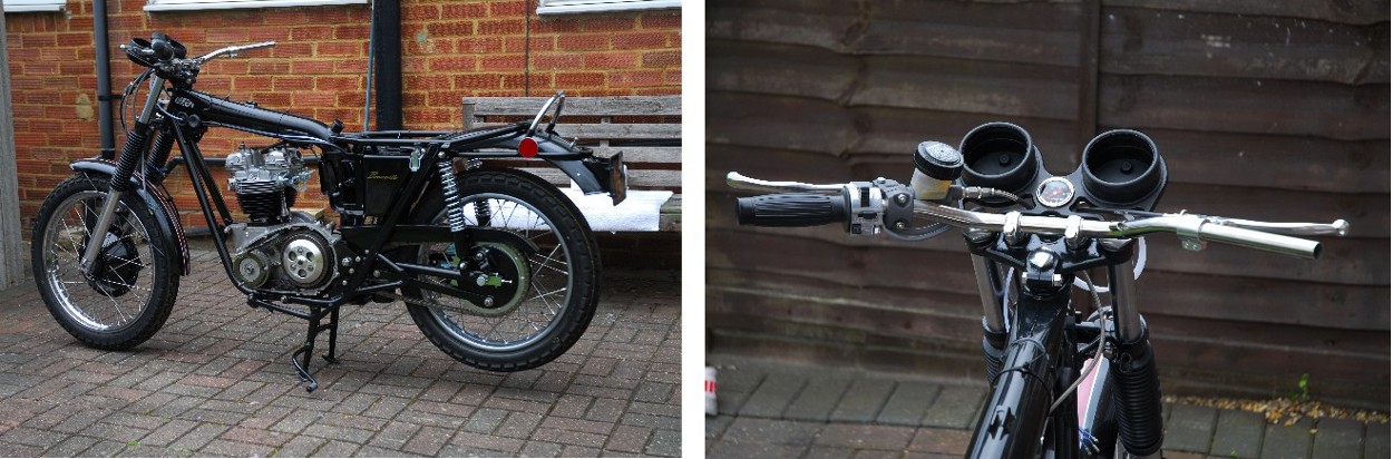
The dismantling has moved on a step further today. Both mudguards have been removed. The front has been repaired at sometime in the past and not very well. It never did look quite right anyway so I'll try and source another one. The wiring harness and headlamp have also been taken off as well as the grab rail and rubber grommets in the frame. There's not much left to take off, now.
29th November, 2014
Stripped the last few bits off this afternoon. That included the stuff on the handlebars, the speedometer, the tachometer and the front brake cable. I also removed the rocker spindle oil feed pipe and disconnected the engine oil return pipe from the frame. The engine oil feed pipe is a bit tricky to get at but that will have to come off before the engine is removed.
30th November, 2014
1st December, 2014
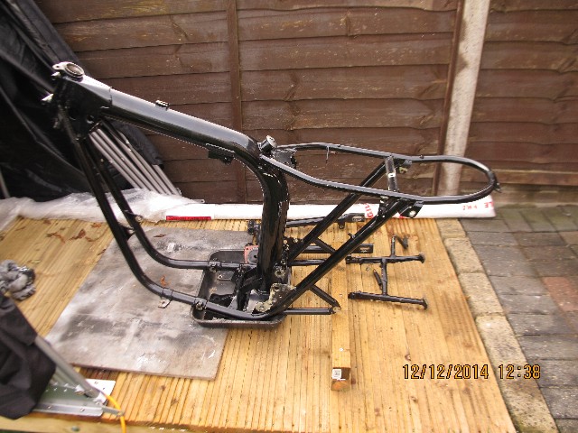
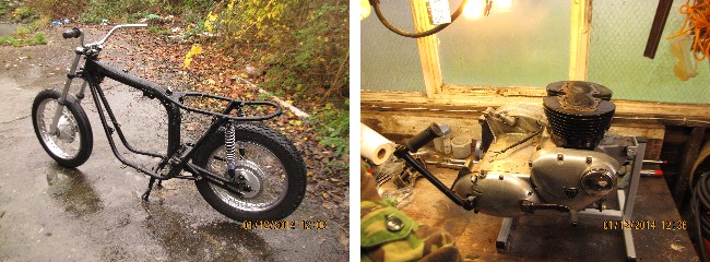 This morning I rolled the chassis out onto the back access road for a cleaning session. Half a can of 'Gunk' was brushed into the accumulated road muck, oil and assorted dead wildlife that had collected on the lower regions of the frame. This was allowed to soak for a while then it was blasted off with a pressure washer. The result was quite pleasing. After drying off the excess water, the chassis was rolled back into the yard and will be further dismantled for bead blasting and powder coating in due course.
The rocker boxes and cylinder head were degreased with white spirit and dried. Then they were packed up and tomorrow they will be on their way to SRM Engineering in Wales to be reworked and soda blasted. The rest of the engine has been installed in it's work stand and will be taken apart, inspected and reassembled in due course.
4th December, 2014
The wheels, fork legs and steering yokes came off today. I started off by undoing the four cap retaining nuts at the bottom of each fork leg and removing the spindle retaining caps. The front brake plate anchor nut was next and the front wheel removed. The spindle nut that retains the brake plate to the hub was only finger tight and came undone easily... probably too easily. The brake plate assembly was lifted off the hub and put to one side for strip down and cleaning.
The fork cap nuts were already loose from when I removed the speedo and tacho so they came off easily. The pinch bolts in the bottom yoke were removed and with a little persuasion, the fork legs slid down out of the yokes. These were inverted in a tray to drain the oil. They are in very good condition and apart from polishing up the aluminium sliders, I don't think any work is necessary. The top yoke pinch bolt was removed and the large chrome retaining nut removed. The two yokes were then separated from the frame. The taper roller bearings look to be in good condition also and won't need replacing.
The rear brake plate torque arm bolts were undone and the torque arm removed. This just left the rear wheel spindle which needed a tap with a plastic faced hammer to remove. One problem noticed... the bearing retaining lock ring on the brake drum side has a stripped thread and was loose enough to fall out. Fortunately, the thread in the hub looks OK but I will need to source an new retaining ring. [EDIT: This proved to be a continuing problem as the thread in the hub was not as good as I'd thought. The problem was only fully resolved 9 years later when I replaced the complete rear hub. (See Part 2)] I took both wheels over to Les at The Two Wheel Centre and he kindly removed the tyres for me on his pneumatic machine. It was worth a couple of quid to save my blood, sweat and tears as the tyres had been in place since 1989 and were very hard.
5th December, 2014
Today was the first day of working in the shed. The front rim was un-laced from the hub. The rim was given a bit of a polish and the stainless spokes cleaned. Then the rear wheel was treated the same way. I may try to get some money back on them by offering them on eBay.
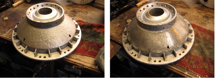
The undamaged bearing lock ring on the none-brake-drum side of the rear hub was unscrewed... NOTE: left hand thread... The lock ring on the brake drum side had already fallen out as the thread had stripped. The rear wheel bearings, grease retaining caps and spacer were tapped out after heating the hub with the hot air gun. The bearings are completely shot and will be replaced. The front hub was now dismantled. The bearings, grease retaining caps, locking ring... NOTE: also a left hand thread... and both circlips were removed after heating the hub. The inner grease retaining cap on the none-brake-drum side was damaged in the removal process and will be replaced. Both the bare hubs were degreased. The brake plates were dismantled and cleaned. The brake shoes have little wear and will be re-used. The paint on the front hub has 'bubbled' and I suspect that the alloy has some corrosion underneath the paint. The paint was removed and although there is some corrosion, the hub looks to be in good condition with no serious pitting. I'm sure the soda blasting will remove what corrosion there is and leave the casting smooth and suitable for the new powder coat.
8th December, 2014
Today is important. It sort of marks the end of the 'taking apart' and the start of the 'putting together'. Apart from separating the swinging arm from the frame, the majority of the dismantling is pretty much finished. This morning I drove up the M1/M6 to Central Wheel Components at Coleshill. There I dropped off the two hubs and two brake plates. They will be soda blasted and then powder coated gloss black prior to having two new stainless steel rimes laced on. I feel I'm actually getting somewhere now.
12th December, 2014
The final parts were taken off the frame today. The rear suspension struts, centre stand and swinging arm followed by the sump plate and strainer from the oil tank. Now it's a case of cleaning the tank out as best I can with white spirit and petrol; then I can mask off the areas that need masking and arrange to get the frame and swinging arm powder coated.
16th December, 2014
Today I cleaned up all the parts that I'm taking for powder coating... That includes the frame, swinging arm, centre and side stands, rear brake torque arm and operating arm, chainguard, the two rear engine mounting plates and the two silencer mounting brackets. The main frame tube oil tank was flushed out with two lots of white spirit and finally with petrol. The steering head bearing outer rings and packing pieces were also removed from the frame. The oil feed connections were blanked off with high temperature, thick wall silicon rubber tube to stop any of the blasting media from entering the oil tank. All being well, I'll get all the bits up to Powder Coatings Ltd, in Birmingham sometime before Christmas.
19th December, 2014
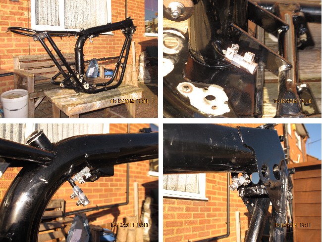
Today I set off early to take the frame etc. up to Birmingham to be powder coated. A nice easy run and I had no difficulty finding Powder Coatings Ltd. Met up with Roger Murphy and a guy named Chris who took all the stuff in. It should be ready to collect on the 9th January. Now we're getting somewhere...
9th January, 2015
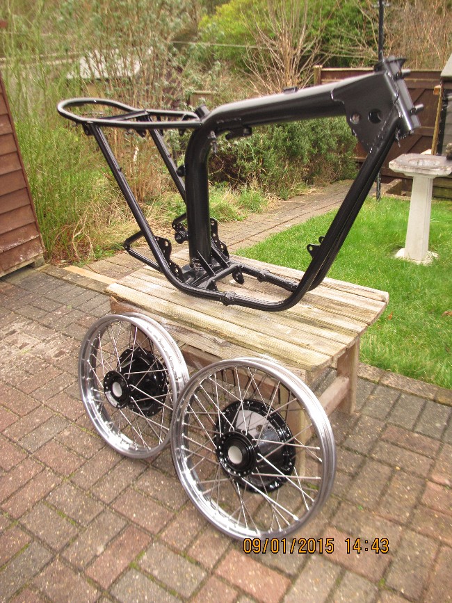
Have got Christmas and the New Year celebrations over and done with, it was time to start on "Daisy" again. Today I drove back up to Birmingham to collect the frame etc. from Powder Coatings Ltd and to Central Wheel Components Ltd. to collect the wheels. I also dropped off another batch of bits to be powder coated. That's the air boxes, side panels, tail lamp mounting and the bits under the seat. They should be ready next week.
18th January, 2015
Things have moved on a pace. I've collected the second set of bits from Powder Coatings Ltd and there was a problem... The left hand air filter cover had, at some time in the past, had a bit of a clout and was subsequently repaired with epoxy filler and resprayed. It was a good repair as I hadn't noticed it at all. It wasn't until the cover was sand blasted that it showed up. Consequently, it wasn't powder coated.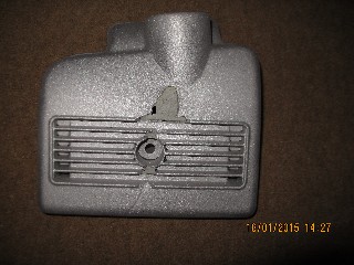 A quick search on eBay produced only one air filter cover and that was an expensive and tatty item in America. By the time I'd had it posted to England, paid import duty and VAT plus the cost of getting it prepared and powder coated, it would have been one very expensive cover. I spent a good hour and a half on the phone to various classic bike breakers and most of the shops that dealt with old Meriden Triumphs all to no avail. Then I spotted an advert for Reg Allen's shop in Hanwell, London. I gave them a ring and what do you know... They had a brand new old stock cover, already painted black which I could have for the princely sum of £31.50 plus delivery. I was a very happy bunny again!! Anyway... the wheels had now been built up with new bearings and have been fitted with new TT100 tyres; a 3.60x19" on the front and a 4.10x18" on the rear. A new sprocket was bolted to the rear hub with stainless bolts and locking nuts. The brake plates have also been reassembled and I reckon they look good in black rather than the original siver. The more knowedgable among you will have noticed that the front brake operating arms aren't standard. The pressed steel standard items have been replaced with custom made arms, machined from solid stainless steel. They are much stronger and also 1/2" longer between centres which will give more leverage and hopefully better braking.
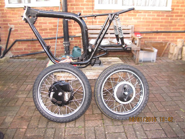 Today was bright sunshine again and not particularly cold so I started to reassemble the frame. The swinging arm was fitted first with a new stainless steel axle stud and nuts. I'd taken the springs off the rear suspension units and repainted the bodies. They were fitted with new chrome springs from Alf Hagon and have now been refitted to the frame. The side stand and centre stand have also been refitted. All in all, things are coming together nicely.
19th January, 2015
Today's job is to fit the new steering head bearings and the front forks. The bearing outer rings had been in the freezer for a few days so they were nice and cold. I warmed up the bearing tube on the frame with a hot air gun and the outer bearing rings with their associated packing washers tapped into place nicely. The top and bottom yokes were fitted into place with the new bearings and dust cover. So far, so good.
It took a little swearing and some knuckle skin but I eventually persuaded the new rubber gaiters to stretch over the fork sliders. They weren't fitted as standard but I think they look better and also protect the stanchions so they were fitted. Actually, they are Norton Commando items but if you don't tell, I won't. Fitting the fork legs into the yokes was another matter entirely. They were a bit on the tight side coming apart so I was expecting a fight to get them back together. Actually, it wasn't too bad. The bottom yoke was opened up with a tapered wedge and with a liberal application of grease and rubber mallet, they went together without too much trouble. I'd already obtained the new speedometer drive for the back wheel to replace the broken one mentioned up the page a ways. I'd also obtained a new spindle and lock nut. The wheel went back in without any hassle. 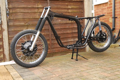 It was obviously slightly out of static balance but two small five gram weights on the rim sorted that out perfectly. The front wheel was no problem but I'm just not happy with the way the front mudguard fits. It's much too far away from the wheel. Not exactly sure what I'm going to do about it but it will be sorted to my satisfaction in due course.
20th January, 2015
The new air filter cover arrived today. It had been sprayed black on the outside but the paint was very poor and the aluminium was showing through in the corners of the fluted panel. I didn't want to make another journey up to Powder Coatings Ltd so I took it Markell Ltd, on the outskirts of Luton, just a few minutes drive away. Spoke to a guy named Jack who showed me around the place. Quite a nice set-up and they do quite a lot of bike stuff so I was happy to leave the cover with them to coat gloss black. Time will tell if that was a good decision or not.
3rd February, 2015
Things have moved on yet again. The new air filter cover was coated perfectly at Markell Ltd. Only problem was that they only coated the outside. Probably my fault for not asking them to coat it all over. No big deal, I'll give the inside a coat of primer and black gloss from a rattle can. The front mudguard was a little more problematic. I cut through the weld securing the stays to the rear of the blade and ground away all the old weld and paintwork. The stays were then re-bent to enable the guard to sit closer to the tyre and then they were welded back to the blade. I'm happy now and will be taking the two mudguards and the tank to be repainted by Colin at 'The Finishing Touch Classic Motorcycle Paintwork' in Chelmsford in due course. My wallet will be considerably lighter when they're done!!
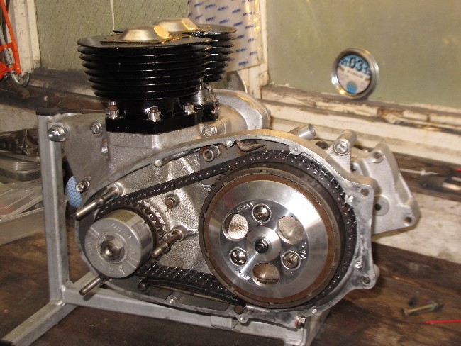
I've started to take the engine apart. The barrels have been lifted off the crankcase. There appears to be very little wear and checking with an internal micrometer confirmed that the bores are within tolerance for the 'standard' bore size. I'll hone the bores lightly to break the glaze and I have a new set of 'Goetze' piston rings from Germany. The pistons showed very little sign of wear although when the carbon was cleaned off the top, the left piston showed signs of old corrosion. I think that this bike had been left standing for some time with the plugs removed and damp had got into the engine. It's not enough to warrant new pistons and has mostly polished out ok. Just to confirm that, SRM Engineering contacted me yesterday to say that they had also found traces of old corrosion on the cylinder head, once the carbon had been bead blasted off. Again, not enough to worry about as they will polish it out.
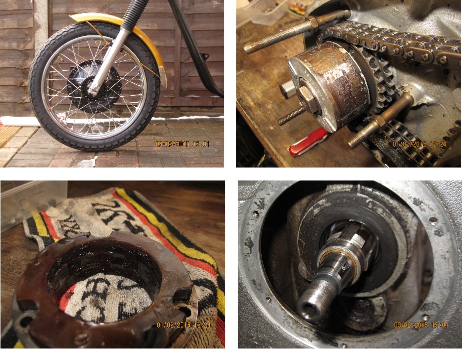
The primay drive has been stripped off. The primary chain was worn and very slack. There was evidence of it hitting the alternator securing stud. The chain tensioner blade was also badly grooved. The sprockets, however looked to be in good shape so they will be re-used. The chain and tensioner blade will be replaced. The clutch has been upgraded from standard as it now has seven plates instead of the normal six. All the plates, the clutch hub and the basket are in excellent shape and will be put back as they are. I did, however find that the primary drive cover has been damaged. It looks like the same coming together with the road that damaged the side panel, also bent the left side front footpeg enough for it, in turn, to cause a dent and a crack in the cast aluminium primary drive cover. Bummer....
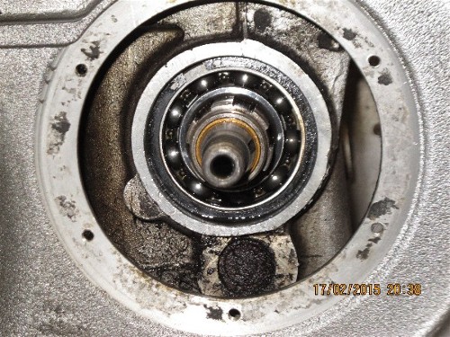
There is also a problem with the alternator... There are a number of radial cracks in the plastic insulation. It looks like the stator has been getting hot, causing the the insulation to swell. There has definitely been contact between the rotor and the stator insulation as the plastic potting has been smeared around the inside of the stator and the outside of the rotor. The rotor will clean up ok but I'm not going to mess about with that stator... I'll just replace it. I wasn't very happy with the output from the electronic regulator when I measured it some time ago. Possibly, the regulator is faulty and that is what caused the alternator to overheat in the first place so I'll replace that as well.
With the primary drive out of the way and the gearbox final drive sprocket removed, I can get at the faulty gearbox oil seal. Hopefully, I'll be able to get the old one out and a new one in without having to disassemble the gearbox. That would be really handy.
17th February, 2015
 After spending a relaxing few days in deepest Surry, cat sitting for my ex-wife and her partner while they were on holiday in Tenerife, (how come I get all the good jobs?), it was time to put some more hours into the Bonneville rebuild.... While I was away, the cylinder head and rocker boxes came back from SRM Engineering. The head has been vapour blasted prior to having new valve guides fitted. The exhaust valve seats have been replaced with hardened steel items that are suitable for use with unleaded fuel. The valve seats have been recut on their Serdi machine and new plasma hardened valves fitted. New springs completed the assembly. The rocker boxes have been stripped, cleaned and re-assembled with new spindle o-ring seals and new adjusting screws. Excellent. The new primary drive cover to replace the damaged one has also arrived as did the stainless bits and pieces that I'd been waiting for from Andy Molnar. Now we're cooking with gas!
OK... the barrels have been cleaned, honed to break the glaze and given a fresh coat of high temperature black engine paint. There is very slight evidence of wear but certainly not enough to warrant a re-bore, which is very good news. The gearbox oil seal gave up without much of a fight.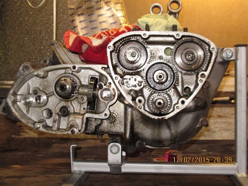 I drilled three, 3mm holes through it and screwed in three self tapping screws. As they came up against the bearing retaining circlip, they pushed the old oil seal out... easy, peasy. That means I don't have to strip the gearbox... more good news. I can detect no sign of any play in the big end bearings or the main crankshaft bearings, both of which seem very smooth so I've decided against splitting the crankcase. There is no sign of any oil leak from the crankcase joint so I'll go by the old engineering adage... "If it ain't broke, don't fix it 'til it is!" and leave well enough alone.
I removed to old Boyer ignition rotor from the end of the exhaust camshaft and then removed the timing chest cover. All seems OK in there, there's no discernable play in either of the camshaft bushes or the idler wheel bush. I have a new L.F.Harris oil pump to go on, so I took the old one off. I also have new oil seals for the timing cover but I won't replace them until I've buffed up the cover to give it a bit of a shine. The gearbox outer cover also came off as I want to replace the cable clutch mechanism with a hydraulic cylinder. I'll check the gearshift pawls and springs and replace anything that looks worn. That cover will get the polishing treatment as well.
22nd February, 2015
I had an hour or two spare today so it was back into the workshop. First job was to remove the two old oil seals from the timing cover. The oil seal for the exhaust camshaft / ignition points compartment knocked out easily and after removing the circlip retaining the crankshaft oil seal that was removed as well. The cover was cleaned with white spirit followed by a good 'Gunking' and a hot soapy wash. I've been dithering about fitting an external oil filter. The easiest and most common way is to fit a screw-on cartridge filter in the oil return line to the tank but my engineering knowledge and experience tells me that this isn't the right way to do it. You should be FEEDING clean filtered oil to the engine, not filtering the oil coming back from it. With this in mind, I'm going to send the timing cover up to Kirby Rowbotham and get his conversion done... If you're gonna do it, do it right first time.
With the timing cover finished, it was time to look at the gearbox outer cover. First job was to get the kick-start arm off the spindle. What a bastard job that was! The cotter pin was in solid and only an extreme method (which I'm not going to discuss here!) enabled me to remove the kick-start arm. Having removed the kick-start arm, I found out why it had been so difficult to get off. At some point in the bikes past, the cotter pin had been put in the wrong way round. This meant that the force exerted on the kick-start to start the bike had forced the threaded end of the cotter pin into the axle and distorted it. When a new cotter pin was subsequently put in the correct way round, the damaged axle had in turn damaged the new cotter pin making it almost impossible to remove. Anyway... job now done. The kick-start axle/quadrant assembly and return spring were then removed from the case. A new axle will be required. There was no sign of any oil leakage but I'll renew the oil seal as a matter of course. The gearshift mechanism was dismantled and checked. The pawls are in good condition but I'll renew all four springs and the 'O' ring on the gearshift shaft. The clutch operating bits and pieces were also removed. They will be replaced with a hydraulic slave cylinder. The cover was then cleaned in the same way as the timing cover. Both the timing cover and gearbox outer cover were given a good going-over on the buffing wheel. It's not perfect but I'm happy with it and a little 'patina' is good on an old bike!!
26th February, 2015
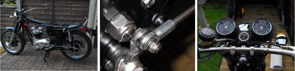
Today I set about installing the hydraulic slave cylinder for the clutch. It wasn't difficult but it did involve a bit of 'phaffing about'. 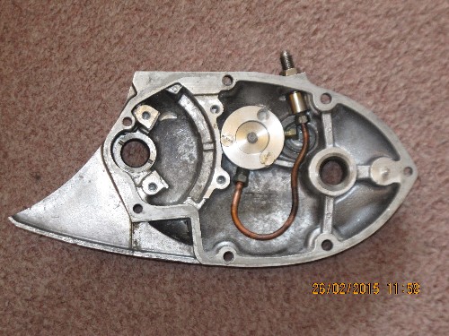 To get the stainless adaptor to fit nicely into the top of the case where the cable adjuster would normally be I had to gently remove some of the aluminium casting with a die grinder. I was acutely aware of how much I was removing as I certainly didn't want to 'break through'. The edges of stainless adaptor were also radiused to fit the reworked casting. It took about an hour of removing tiny amounts and trial fitting before I was happy. Once that was done and the cylinder screwed to the case using the same locations as the original 3 ball mechanism, it was a matter of bending the copper pipe to fit. The copper was pretty hard so I had to anneal it by heating it to cherry red and quenching it in cold water. That done, it was simply a case of bend and fit until it was right. I'm quite happy with the result and I think it's fitted fairly well.
As I've bought a CNC machined SRM aluminium clutch pressure plate with a roller thrust race to compliment the hydraulics, I'll have to make a shorter clutch push rod. I didn't want to cut the original so I've ordered a 13" length of 7/32" diameter 'silver steel'. I can cut this to the correct length, polish the ends and then harden them by heating to cherry red and quenching in my dwindling supply of whale oil. Slowly but surely, things are progressing.
16th March, 2015
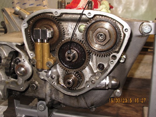 Having taken some time off to indulge one of my other passions, namely pike fishing on one of Norfolk's shortest rivers... the River Thurne, it's time to get back to rebuilding the Bonneville. Colin from Finishing Touch 'phoned while I was away to tell me that the tank and mudguards would be ready for me to collect next week. That's good news. So... what have I done since the end of February? Actually, not a lot. The timing gears have been re-assembled and the camshaft nuts tightened to 60 ft/lb of torque. I couldn't find a factory recommended torque figure but 60 felt about right; they're left hand threads so I don't expect them to work loose. A new LF Harris oil pump has been fitted along with a new stainless steel pressure relief valve.
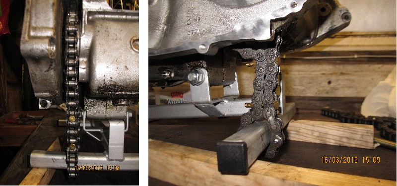
On the other side of the engine, the damaged alternator mounting stud has been replaced and a new oil seal fitted to the gearbox final drive. The new final drive sprocket was a tight fit on the output sleeve but a little gentle persuasion pushed it into position. A new locking tab washer was slipped on and the securing nut screwed up finger tight. Now all I had to do was work out how to stop the sprocket turning whilst I finally tightened the nut. They say that 'necessity' is the mother of invention but I reckon that striving to get your nuts tightened comes in a close second. Actually, once I'd thought about it for a few minutes, it was really simple. A short length of old final drive chain was looped around the sprocket and one of the tubes of the engine support frame. A couple of 6mm diameter bolts through the two runs of chain and that was that. The securing nut was fully tightened and the tab washer bent onto one of the nut's flats to finish the job.
24th March, 2015
The timing cover has come back from Kirby Rowbotham suitably modified for the oil filter kit. I have hit a minor snag, though. The oil return line from the filter enters the timing cover through what was the oil pressure switch location. The switch will be re-located to the oil filter plate but I also need somewhere to tap off for the oil pressure gauge that will be fitted between the clocks on the top of the forks. This means that I'll have to drill and tap another hole in the oil filter plate. Not difficult, just another job to add to the list. The timing cover joint has been sealed with 'ThreeBond' and the cover screwed back onto the crankcase.
A minor calamity... I've broken a bit. I had intended to re-assemble the primary drive but before doing so, I screwed in the sleeve nut that takes the alternator wires through the rear of the chaincase. Unfortunately, the bloody thing snapped off, leaving the broken threaded portion firmly stuck in the crankcase.
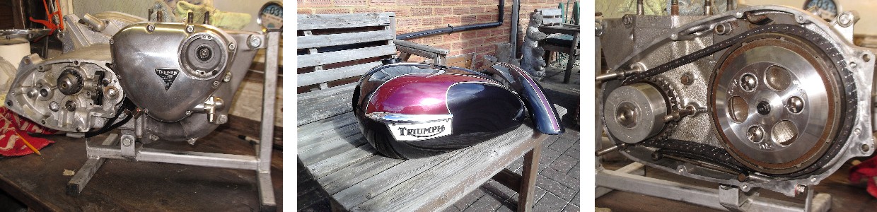
Colin let me know that the tank and mudguards were finished so I've been down to Chelmsford to collect them. Very smart they are, too, in their new colours of metallic black, which I understand is a Volkswagen car colour, and a Hinckley Triumph colour "Astral Red".
30th March, 2015
 The broken bit of sleeve nut has been successfully removed and the new nut installed. The primary drive has been reassembled with a new chain, new chain tensioner blade and a new lock-nut on the clutch mainshaft. I've also used a new nut and tab washer on the crankshaft to retain the rotor, which has also been cleaned up to remove the plastic from the stator that had been smeared around it. The clutch pressure plate is new; that's a CNC machined alloy job from SRM and uses a roller bearing thrust race. The spring cups, springs and adjusting nuts are also new. I've made a new clutch pushrod from a length of high carbon 'silver steel'. After some careful measurements and some double checking, I cut it and ground the ends to give me a length of 260mm. The ends were then hardened by heating to 'cherry red' and quenching.
I'd already obtained a new set of German "Goetze" piston rings so they were checked for end gap by fitting them into the newly honed cylinder bore. The gaps were all very slightly larger than ideal (about 0.015" instead of 0.012") but perfectly acceptable as they were being checked in the most worn part of the bore. The rings were fitted onto the pistons and the pistons re-fitted to the connecting rods using new circlips. New tappet blocks have been fitted to the freshly painted cylinder block. The cylinder block was fitted over the pistons and bolted to the crankcase with a new gasket and new stainless steel 12 point nuts. That's just about it. The engine is ready to be dropped back into the frame (How easily that phrase trips off the tongue. I don't suppose it will actually be that easy!). It's a bit heavy to do single handed so I'll have to encourage (bribe) my mate Les to come round and give me hand to do that.
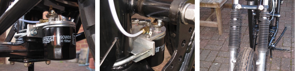
31st March, 2015
I only had a couple of hours to spare today so I've fitted the new oil filter that Kirby Rowbotham supplied. It fits behind the main frame tube, below the swinging arm. It's neat and out of the way but perhaps a bit vulnerable. That's all the good news... The bad news is that the gaiters that I fitted to the the front forks have fallen apart... bummer. That means that the front forks have got to come off again. At this point, I'm not sure whether I'll replace them or revert back to the short dust covers that were fitted originally. It depends if I can obtain some better quality gaiters. Ho hum... one step forward, three steps back.
13th April, 2015
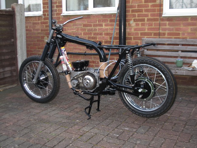
Having had a bit of a break, namely to go hiking over the North York Moors for a few days followed by a weekend at the Banbury Folk Song and Ale event, it was time to start on the bike again. I've obtained a new set of front fork gaiters from Andover Norton. These are of a noticeably better quality that the pair I bought previously but were a little more difficult to fit. Softening them in some hot water enabled me to stretch them over the fork sliders, thought. That done and the forks refitted to the frame it was time to reinstall the engine... or most of it, anyway. Les came round this evening and lent a hand... Thanks mate. It went in remarkably easily and only took a few minutes.
14th April, 2015
It's been another "one step forward and two steps back" day today. I fitted the new oil lines to the engine and the oil filter, which was easier than I expected with the engine in position. The rear engine plates were offered up and finally tighten along with the two main engine location studs; the shorter front one and the long one under the engine. That done, I set about fitting the cylinder head. I'd bought two new machined alloy pushrod tubes to replace the rusty steel items that were originally fitted and they looked really nice; what's more... they fitted. The cylinder head was bolted on and torqued up to the correct figures with new stainless steel bolts. However.... when I tried to locate the new chrome-moly steel pushrods onto the cam followers there was a problem. It turned out that the internal diameter of the pushrod tubes was too small by at least 0.030" and the pushrods were fouling on the inside of the tubes. The whole lot had to come off again... Bummer! Rather than scrap the tubes or grind a bit off the pushrods, I took the tubes over to Belmont Engineering in Hitchin and they are going to bore them out for me. I've used them before when I needed some work done on some Guzzi bits. It will take a day or three but I have enough to be getting on with in the meantime. I contacted the supplier and complained about the tubes not being 'fit for purpose' and they agreed to a partial refund which will go towards offsetting the cost of the corrective machining. Ho hum...
 21st April, 2015
Things have moved on again over the last few days. The mudguards are on as are the air filter boxes, although they may need to come off again when I start on the wiring but it's only a couple of screws. The final drive chain is on and the instument 'panel' has been mounted on top of the front forks. That's the good news. The bad news is that I've hit a snag with the front brake cable. I'd bought one from Venhill Cables and as I'm not intending to use the original switchgear/brake lever on the right hand handlebar, I also bought a new brake lever from Venhill as well. It seems that Venhill's right hand doesn't know it's left hand is doing as the cable didn't fit the lever. Oh well, nobody said this rebuild was going to be easy. An hour or so's work in the shed with a set of Swiss files and I'd got the cable nipples to fit both the lever and the front brake operating arms. That's when I found out that the brake light switch that's built into the cable didn't work either. Don't you just hate the crap quality of British components... give me the Chinese stuff that works every time!! Having taken the cable off again, I found that the staked on top part of the switch had become un-staked, allowing the switch to fall apart. I've put it all back together and used epoxy adhesive to secure the 'lid'. Hopefully that will be all that's necessary.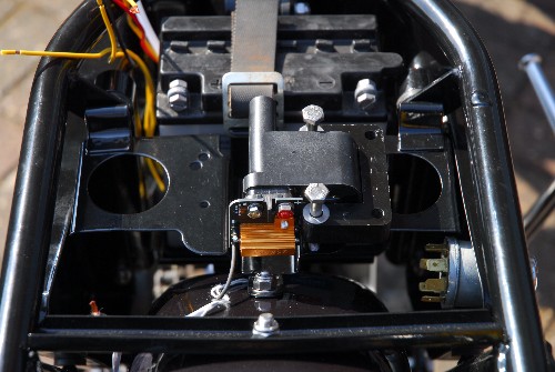
While I was waiting for some stainless screws to be delivered, I had a look at mounting the new dual spark ignition coil that came with the C5 ignition system I imported from America. Because of its shape and the position of the mounting holes, the only place I could find to mount it was on the plate that held the original twin coils under the seat but I had to loose the little tool tray that should be attached behind it. I'll need to obtain a couple of short spacers to mount it on but that shouldn't be a problem. What was a problem was the fact that the special HT leads that came with the kit weren't long enough with the coil mounted under the seat. When I say 'special', I mean SPECIAL... The C5 manufacturers were very specific about what HT cable could be used. Of course, it's American... Moroso 'Blue Max' spiral core with a resistance of 800 ohms per foot. An internet search only produced one supplier in the UK. Fortunately, they were not a million miles away so I drove down to deepest Middlesex to locate an outfit called 'Real Steel' who specialise in selling performance and customising components for American V8 engines. I was hoping that they would be able to make me up a pair of custom leads. Yeah... right. This is Britain, remember? Customer service is none existent. They would sell me a boxed set of leads for a V8 for 70 of our fine English quids but didn't do 'custom' stuff. What sort of customising component shop is that?? What they did have, however, was 'Coil Lead Kit' which comprised a 30" length of Blue Max cable and a small assortment of crimp-on connectors, none of which were any use to me. That would do... I would have to crimp on my own terminals but I now had enough stuff to make up a pair of leads that would be long enough.
26th April, 2015
We've moved on again... The bored out pushrod tubes were collected from Belmont Engineering a couple of days ago. They've done a satisfactory job on them and the pushrods now locate on the cam followers as they should. The top end of the engine has been re-assembled with a new 0.080" thick copper head gasket. This gives a 'seal crush' of approximately 0.035" with the thicker of the two seal options which is spot on middle limit. The hydraulic clutch kit has been installed, bled and set up to lift the clutch pressure plate 0.10" for a full squeeze of the lever. This looks about right and frees the clutch nicely. As the master cylinder is an AP Racing adjustable delivery item, I can increase or reduce that lift if necessary. Before bolting on the gearbox outer cover, the screw-on canister oil filter was filled with fresh 20w50 oil and the new oil lines to and from the filter were primed with oil. This should mean that oil will be delivered to the crankshaft as soon as the engine is started.
The new three phase alternator stator has been installed and connected to the Podtronics solid state rectifier/regulator unit. It was a bit tight getting the cable through the two grommets that seal the primary drive case but it all went well enough in the end.
5th May, 2015
I've managed to get a few more hours in during the last week and I'm happy to say that things are progressing nicely. The primary drive cover has been bolted back on along with the foot rests. The rear brake operating linkage caused a few moments of anxiety as it wouldn't fit. I'd assembled the swinging arm with a new stainless steel pivot stud and 'Nyloc' nuts. These nuts are thicker than the original fitment and jammed the brake operating lever. I fixed it by adding a thin spacer behind the lever pivot and using a 'rose joint' on the brake rod instead of the original method which was simply a bend and a split pin. Much nicer, I feel.
I've also taken off the front brake cable that I had problems with when I installed it. The brake light switch gave a very 'spongy' feel and was physically too big. It made routing the cable behind the headlamp difficult. As bikes first registered before 1986 are only required to have a brake light operated by one brake, I've changed the cable for a new one that doesn't have a switch. That gives a much better feel to the brake and is easier to route smoothly behind the headlamp. The coil, fuse box and two relays for the halogen headlamp have all been installed under the seat and the new electronic speedometer and tachometer have been fitted into the 'instrument panel'. The headlamp shell polished up really well so that has been reused. The original mounting wires were too rusty to reuse so they have been replaced, as have the indicators.
I've ordered a complete new exhaust system from Armour Motor Products as the old one was past saving. That should arrive this week, sometime. Also ordered are a pair of 'Premier' rebuild kits for the Amal carburettors and a set of throttle and choke cables. The carb bodies are currently with T & L Engineering Ltd for a soda blasting session. Hopefully, they'll clean up nicely. It seems I can't put it off any longer and now I must start on the wiring... I may be gone some time!
18th May, 2015
 Real life and the weather have been getting in the way a little bit recently but progress has been made. The new exhaust system from Armour eventually turned up over two weeks after I ordered it. Not good for something that they said was in stock for immediate delivery. It also took a couple of 'phone calls to get them moving. The pipes and silencers look to be of excellent quality and I'm very pleased with them. The finned clamp rings for the cylinder head, however, were a different kettle of fish entirely. They were total rubbish... rough castings and they'd not been cleaned properly before plating as the chrome was completely absent between the fins. They've been returned for a full refund. In the meantime, I've sourced a pair of machined stainless steel items from America. Certainly more expensive but in a whole different quality league altogether. Don't suppose I'll see them for a couple of weeks, though.
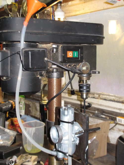
The carburettor bodies have been soda blasted and have cleaned up a treat. I've re-built them with new 'Stay-Up' floats, Viton tipped aluminium float needles, main and needle jets. The slide needle has also been replaced as have the gaskets, o-rings and screws. They've been set up on a make-shift assembly utilising my bench drill to set the fuel level in the float chambers. The new floats only needed a slight 'tweak' to get the correct fuel level of 0.170" - 0.240" below the float chamber rim. They're now ready to be bolted onto the cylinder head. I've sourced all new throttle and choke cables to compliment the rebuilt carbs.
The wiring has also progressed nicely. There just remains a few connections to be made in the headlamp. I've been checking the circuits as I go and have had no problems so far. The rear light cluster and indicators are all working correctly as are the relays for the headlamp main and dip beams. It's now just a case of finishing the connections for the electronic instruments and the warning indicator lamps.
21st May, 2015
The new wiring has been completed and appears to be working correctly.... Well, no fuses blew, anyway which is a good sign. The lights and indicators all work correctly as does the horn and rear brake light. When the ignition is switched on, the needles on the speedo and tacho sweep round the dial and return to zero exactly as they should do and the odometer is reading "00000"... splendid. I still need to program the magic number into the speedometer so that it reads accurately but I have to measured what distance is covered (in inches) for one rotation of the rear wheel before I can do that. Hopefully, the tacho will read correctly straight out of the box as they supply it set up for a twin cylinder engine but as the new ignition system utilizes a 'wasted spark', I may have to adjust it by a factor of two. Time will tell.
Now that I have power on the ignition circuit, I can set up the timing on the C5 electronic ignition system. It should be straight forward enough; simply a case of setting the engine to T.D.C. and rotating the slotted disc until the timing LED on the C5 is illuminated. Well... that's what it says on the tin, anyway.
23rd May, 2015
Yesterday... Hmmm... It all started out OK; the C5 ignition was a doddle to set up. Set the engine to T.D.C. using the Triumph service tool that screws into the crankcase and locates in the notch in the crankshaft. Rotate the slotted disc until the timing LED on the C5 module is illuminated and tighten up the retaining bolt. Check that is hasn't moved and Bob's yer dad's brother! Brilliant. I'm a happy bunny. Thinks to myself that I really ought to check that there's a spark before I go any further so I connect the coil, push a couple of new spark plugs into the HT leads and lay them on the cylinder head. I give the kickstarter a couple of hefty prods and... nothing. Bugger. No spark. At this point I'm a very unhappy bunny.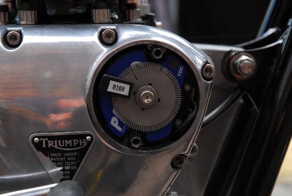
Back to square one... I recheck all the electrical connections and the C5 timing. The battery is fully charged and showing 13.5 volts off load. Every thing looks fine. I kick the engine over again... still nothing. Deep gloom descends and I'm not sure what to do next so I email Mark in America. He's the guy who supplied the kit in the first place. Within half an hour I have a reply back from him. He's been in touch with Paul Crowe at C5 (the manufacturers) and has come back with a check list of suggestions. Based on the assumption that if the timing LED on the C5 module flashes as the timing slot on the disc passes through the optical sensor then the C5 module is OK. I recheck that and the LED flashes... that's good. I run through the other items on the check list; mostly bypassing a lot of the wiring harness and connecting the components directly to the battery... still nothing. I begin to suspect that the twin spark coil is duff. The gloom deepens further as I start thinking about the time delay and work involved in stripping the system off the bike and sending it all back to America for replacement... or even more work involved in changing the ignition completely and putting on a locally sourced Pazon or Boyer system. I start to cry... well, not really but you get the picture!
It's while I'm typing a reply to Mark that I have one of those one in a million 'Eureka' moments that happen nine times out of ten in situations like this. The spark plugs need the engine to be electrically grounded so that there is a return path for the HT. What had I done...? Dropped the engine into a freshly powder coated frame, taking great care not to damage the coating.  The engine mounting plates had also been powder coated, bolt holes and all. When I created the wiring harness I never used the frame as the ground return... for anything; all the lights, indicators and horn had a dedicated ground return wire straight to the battery positive terminal. The engine wasn't grounded. I went back to the bike and discreetly ran a heavy wire from one of the engine mounting bolts on the crankcase up to the battery. I switched on the ignition and kicked the engine over again... got a spark... yea!!! In bright sunlight it was difficult to tell how big but it was definitely a spark and I could hear the 'crack' so I'm hoping that it will be big enough to fire the engine. Time will tell once I've got the carbs and exhaust pipes on. The gloom lifts and I'm (relatively) happy again.
On the subject of carburettors and exhausts... Having re-built and set up the Amal Concentrics, I though about bolting them onto the cylinder head but hit a snag. The mounting flange on the carb has an O-ring groove machined into it; approximately 35mm I/D x 2mm wide and 1.5mm deep. The rebuild kit from Amal came with three gasket options. A conventional gasket made from a thin red fibre board, a 1.8mm section O-ring which fits in the groove nicely but only has about 0.010" compression and probably won't seal. The third option is a thicker O-ring, 3.2mm section, but this is only 32mm I/D and doesn't even remotely fit the groove in the carb flange. It seems, however, from reading comments on the Triumph owners forums that this big O-ring is the favoured option. The method being to just place it between the carb and the manifold and bolt the carb on, hoping that it somehow stays in the right place... How stupid is that! I've ordered some correctly sized Viton O-rings (34mm I/D x 2.5mm section) to do the job in a more 'engineering like' manner.
Oh yes... the stainless finned exhaust pipe clamping rings arrive from America this morning. What a lovely job they are; so much better than the rubbish that's available over here.
26th May, 2015
The new o-ring arrived and fit the carburettors nicely. They've now been fitted to the cylinder head with new cup washers, rubber seal and locking nuts. The o-rings were coated with Molykote 111 silicone grease and gave about 1/2 a millimetre compression which should be just about right. I've made up a new set of fuel pipes using stainless braid covered nitrile rubber which is ok for use with unleaded, alcohol laden petrol. The tank has temporarily been put in position but will have to come off again when I fit the throttle and choke cables to the carbs. The new dual seat from Leighton's has also be attached. It's beginning to look a bit like a motorcycle again now.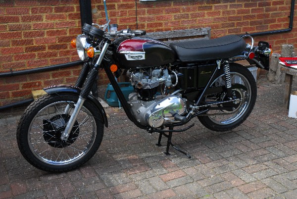
30th May, 2015
Today I spent about two and a half hours fitting the throttle and choke cables. I'm beginning to dislike Venhill cables with a passion! Can it be so difficult for a British company to make something that actually fits without needing modifications? I had trouble with the quality of the front brake cables (two of them) that I fitted earlier. The original one, with a brake light switch incorporated, was so much rubbish that I took it off and fitted one without a switch and even that didn't fit their own brake lever correctly. I ordered the throttle and choke cables from L.P.Williams in the hope that they would be better quality but when they arrived I was disappointed to see that they were actually Venhill cables as well. So... why did it take so long to fit them? Lets start with the throttle cables. First, the nipples on the ends of the inner cable wouldn't fit the Amal carburettor slides; they were two big and needed some work with a Swiss file before I was happy with them. The nipples on the other end were the same and needed cleaning up before they would fit the twist grip. Once that was done and the cables fitted both ends, I found that the inner cable was too short and even with the adjusters screwed fully in, the carburettor slides were being held off the stop screws. The easiest fix was to put the twist grip split ferrules up in a lathe and drill them about 3mm deeper. This gave me a little free play on the cables with the slides fully closed.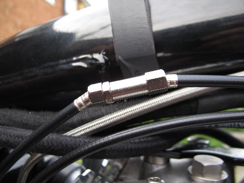
The choke cable was pretty much the same. This is a split cable with a single cable from the handlebar lever to a junction box and two cables from the junction box to the carburettors. The first problem, which I couldn't do much about, was the limited travel of the junction box. It was less than was required for full travel of the choke slides. I could adjust the cables to fully close the choke slides, but there wasn't enough travel in the junction box to allow them to fully open at the other extreme. I had to adjust them so that they would fully open as this was more important and compromise the fully closed position which was less important. Having sorted that out, I found that the inner cable was too short by about 5/8" to fit the handlebar choke lever. This meant some very delicate work with the Dremel and a thin cutting disc to cut through the spiral wound steel outer cover with touching the bowden cable inside it. It was accomplished successfully and everything now seems to work as it should. On the subject of cable adjusters... they didn't fit the cable very well, either. The counterbore in the ends where the outer cable ferrule fits was too big in diameter and not deep enough to locate the cable correctly. I think, in due course, I'll make up my own cables and make sure every component is properly matched but for now I'll stick with these and see how it goes.
6th June, 2015
Today I put the finishing touches to the bike. The 'under tank' cables and wires were tidied up and secured with long cable ties. The polished stainless trim strips were fitted over the tank seam and the tank fitted to the frame. The centre bolt was tightened down and a new rubber plug with 'Triumph' embossed on it was pushed into place to cover up the fixing nut. Looks good. That done, I turned my attention to the electronic speedometer. This needed a 'calibration' number entered. The circumference of the rear tyre was measured... 78 inches. This figure was divided into 63360 to give the number of rear wheel revolutions per mile. That works out to 813, to the nearest complete revolution. This had to be multiplied by the ratio of the rear wheel speedometer drive unit (1.25 to 1). That gave me 1015, which is the number of pulses per mile that the rear wheel sensor delivers to the speedometer head and it's that number that had to be programmed into the speedometer unit. That should be close enough to start with. I'll check it against my GPS receiver and make any correction that's needed in due course.
That done, I filled up her vital fluids. Four pints of Halford's 'Classic 20W/50' was added to the frame tank which bought it up to the correct level. A quarter of a pint of the same was added to the primary drive case and half a litre of EP 80W/90 GL-4 gear oil was poured into the gearbox. The fluid hydraulic clutch reservoir hadn't altered so that was OK. I also poured about 100ml of engine oil into the exhaust rocker box. This drained down into the bottom of the crankcase and will prime the return oil pump. At that point, I had a break for a cup of coffee and a doughnut, courtesy of my next door neighbour, Wanda. It gave the oil I'd poured into the rocker box time to drain down. Suitably sated, I took the spark plugs out and kicked the engine over about a dozen times. I could see oil being pumped back to the tank so the return pump was primed and working. I disconnected the pipe from the Kirby Rowbotham oil filter to the engine and checked that oil was being pumped out as I kicked. It was, so I have every confidence that the oil feed pump is primed and working also. That just left the exhaust system. That went on without a hitch. I assembled it loosely to start with, just to be sure, then lubed all the bolts with copper grease and tightened it all up. That's it, then... finished. I'll get some petrol while I'm out later this afternoon and hopefully, it will fire up tomorrow.
7th June, 2015
No oil had leaked out overnight... which is a good sign. I upended a 10 litre can of premium unleaded in to the tanks, had a final check around the bike for anything obviously loose or not right, crossed my fingers and gave the kick-start a healthy prod. The bike fired and ran first kick... That makes me a very happy bunny!!! It'll need just a little 'tinkering' to get the carbs balanced correctly but all in all, it's looking good. I didn't run it for too long, just long enough to check that oil was returning to the tank and that the gauges were reading correctly. The electronic tacho was showing about 1100rpm at a reasonably fast tick-over and the oil pressure gauge was reading 65psi at tick-over with cold oil. That seems about right. So... project about finished.
It's cost a lot... both in terms of cash and wear and tear on my old nerves and body. I'll probably never get back what I've spent on it... I'm not saying how much but it was a significant amount... There again, that wasn't the object of the exercise. I wanted to take a perfectly good bike and make it better. I think I've achieved that. The 45 year old technology has been brought bang up to date. A first class electronic ignition system, up-rated alternator and solid state charging system, electronic instruments instead of cable driven items and a hydraulic clutch. That's just the main stuff. Add to that all the stainless steel and new paintwork, sweat and tears...
At this point, I would like to thank Mark Mittlestadt and Paul Crowe in America for all their patience and help with the C5 ignition system. Also Andrew ("jhury" on eBay) for his custom stainless bits. There were numerous other suppliers that I sourced stuff from but by far the most Triumph bits came from 'Grins' up in Scotland. Thank you one and all... To quote Vinnie Jones - "It's been emotional."
Will I do another one? What do you think? I've still got a 34 year old Moto Guzzi Le Mans that need sorting... Watch this space.
UPDATE... 30th June 2015.
I think I've finally sorted the carbs. I've had to remove the 'stay-up' floats and aluminium needles and put back the white plastic floats and brass needles. I've also upped the main jets to 200 and lifted the slide needle to the middle notch. I think filling the tank with fresh petrol also may have helped... Whatever, the bike was running fine today. It got very hot while I was caught in traffic (the ambient temperature was in the high twenties centigrade) but the oil pressure remained close to 60 p.s.i. even at idle. I felt the oil filter can when I got home and it was pretty warm but I could still keep my hand on it without getting burned. A good look around the engine showed that so far, it's completely oil tight... No leaks from the pushrod tubes or the rocker boxes. I checked the speedometer against a GPS unit and the speedo was reading about 8% fast so I've adjusted the 'calibration number' in the speedo to correct that. I'll check it again next time out.
Here endeth "Part 1". Daisy's story will continue. As is the way with old motorcycles, Daisy will "evolve" and her continuing story will be told in "Part 2".
Link to Index and Home Page.
Link to Triumph Tiger 90 page.
Link to AJS M18S page.
Link to Matchless G3/LS page.
Link to Matchless G80CS page.
Link to Honda VFR750 page.
Link to Norton 650SS page.
Last updated 07/02/2022