I'm not sure that what I'm about to undertake is a good idea. In fact... it almost certainly isn't but when has that ever stopped me from doing something? It all started harmlessly enough towards the end of October, 2016. A few friends, having enjoyed a good meal, were shooting the breeze around a table loaded with copious amounts of red wine. Malcolm was sitting next to me and as sometimes happens, the conversation drifted around to motorcycles. I knew Malcolm as a folk singer of some repute, I had no idea he was interested in old British motorcycles. It transpired that he'd collected a load bits with the intention of creating a thing of beauty, namely a Matchless G3/LS, during retirement some time in the future. Well... "tempus" had "fugited" as it is wont to do and he finally had to admit that he would never have time to complete the project, other stored projects taking priority. With wine fuelled exuberance I agreed to take the project on... Well, it seemed like a good idea at the time, guv, honest!
 To cut this preamble a little shorter, at the end of February, 2017, a fist full of wedge changed hands, all the bits were loaded into the back of friend Les's Jeep Cherokee and I became their new custodian. [If you'd like to see the stuff I bought from Malcolm, follow this link :- Parts as bought.]. Les thought I'd totally lost the plot and we should take the whole lot straight up to the tip. Maybe he was right... Time will tell.
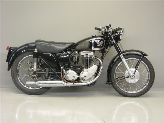
You never really 'own' these old bikes. They're like land... you just look after them for a while and then pass or sell them on to the next fool (currently me!). The photo on the left is more or less what they looked like as they left the factory in the early 1950s. Having had a couple of days to go through the bits that I've acquired, I can safely say that the bike I'll end up with, sometime down the line, will not look like that... at all!
Some of the engine parts and a lot of the tin-ware had suffered from corrosion before Malcolm acquired them and he'd already obtained some replacement parts. A rocker box and cylinder head being chief amongst them. Some restoration work had been started and a few of the smaller part had been repainted and carefully put away for future use. The cylinder barrel and probably the crankshaft, however, look beyond economic repair. The barrel, I can probably replace reasonably easily and without too much expense... I can probably recycle the old one as a mud-weight next time I go fishing up in Norfolk. The crankshaft, however, is a different matter. While I have the skill to rebuild it, I don't have the facilities and to have it rebuild and 'trued' professionally would only be viable if money was no object and there wasn't an alternative. Reality has to temper enthusiasm a little. In the current financial climate, a fully restored G3/LS isn't going to fetch much more than about £4,000 so there's not a lot of point in spending any more than that to put one together. [EDIT... From some some later... £4,000, yeah right!! I'd spent that and more before I'd even got a rolling chassis.]
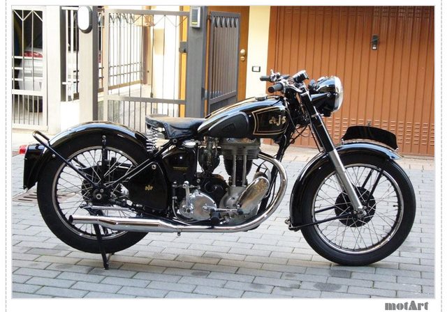 There is, however an alternative... Plan 'B'. Amongst the bits that I've got is an almost complete 1960 500cc AJS M18 engine. It just needs a barrel and piston which I'm currently trying to source. It's in much better condition than the G3/LS motor and it should be pretty much interchangeable with it. There is also the correct AMC gearbox that looks like it's in excellent condition. So... Plan 'B' is to build what is commonly known as a 'Bitza'... bits of this and bits of that! I'll use the G3 frame with a rigid rear end from a slightly earlier era and drop in the 500cc engine and gearbox. Keep it stripped to a bare minimum and hopefully end up with something not a million miles away from the bike in the second photo.
I keep referring to the bike as a Matchless G3/LS but in truth, I don't know for certain that it is. The 350cc engine certainly has G3/LS stamped on it but as I'll eventually have to apply to the DVLA for a new, age related, registration, it's the frame that will determine the 'legal' make and age of the rebuilt machine. The frame had a unique number stamped onto it at the factory and I've already sent details and photographs off to the 'Dating Officer' at the AJS and Matchless Owners Club. They have the factory records and will be able to tell me exactly which make (AJS or Matchless) and model (G3, G80, M16 or M18) of motorcycle that frame was originally assigned to.
Sunday, 26th February, 2017. I had a phone call from the AMOC Dating Officer this morning... No, he didn't want to take me out but he did have some news for me. The frame I have is definitely a 1954 Matchless G3/LS. The better (in some respects) news is that the frame, the 350cc engine and the Burman gearbox that I have were all part of the same original bike as it left the factory. I may have to re-assess my initial thoughts and plans. A 'matching numbers' machine with a Certificate of Authenticity (which I would be able to apply for if I kept all the parts together) means I may be able to recover the original registration number. That would make the finished machine more desirable than a bike cobbled together from an assortment of bits and it would command a higher price should I choose to sell it at sometime in the future. It may be that I will have to re-build the 350 engine and use that after all. It will be more expensive but it does mean that I can keep the 500cc engine as a spare for 'Bess', my '55 AJS M18S. Hmmm........
 Saturday, 4th March, 2017. Some good news and some not-so-good news. First off... I've finished sorting out and photographing all the stuff I've acquired from Malcolm and now have a better idea of just what I've let myself in for. There are a lot of parts that really are just too far gone to be viable. The steel and iron parts haven't coped well with being stored in a damp garage for three decades. That said, there is a lot of stuff that can be recovered. There are also some notable absences, namely a short Lucas E3N dynamo, the 'Jampot' rear suspension struts and some of the Burman clutch parts. They are all expensive items to replace... if you can find them. Remember... this is a 60 year old machine we're talking about.
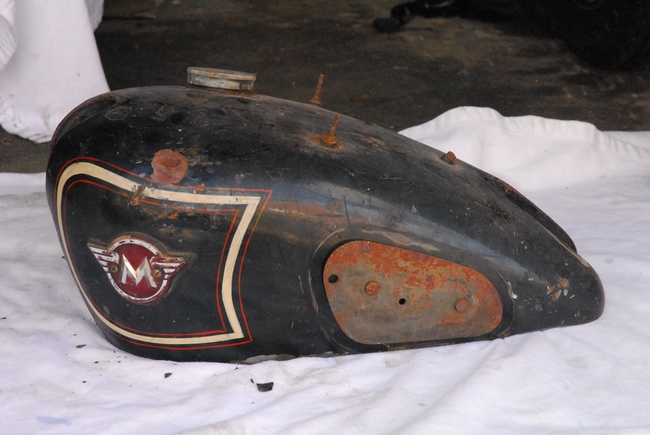
The petrol tank has been... ummm.... modified by a previous owner. There are three bolts in the top of the tank, presumably to mount a carrier or perhaps even some sort of radio unit. Whatever, there are three holes where there shouldn't be any. So... it was with some excitement that I spotted a couple of items that had just popped up on eBay. A tank and a short dynamo. I bid on them and got them for the starting price. The tank was a bit rough and there were a couple of small dents but nothing that will pose a problem for Otto Racs when the time comes to paint it. All in all, I was happy with it. The dynamo was another matter entirely. Yes, it was a short version but it was also a very old version. It was also definitely not working. Having spoken to Paul Dunn (who knows about these things) I've decided that it's not a viable item to refurbish so it's going back onto ebay.... "Caveat Emptor", as they say!!
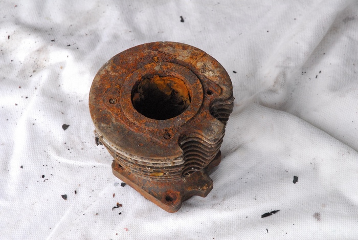 Monday, 6th March, 2017. An interesting day. I had another look at the cylinder barrel and it's perhaps not as bad as I first thought. Maybe I'll have to find something else for a mud-weight after all. I attacked the top and bottom with a wire cup brush on my angle grinder and cleaned off most of the rust. The bottom joint face and skirt are in surprisingly good condition. The top joint faces are a bit worse but probably usable. Having poked what remained of a balled up lump of cloth out of the bore, I had a go at removing some of the rust and corrosion with a hand held wire brush. It is a bit rough. I measured the piston that came with it and unsurprisingly, given that it's an original wire wound job, it's 'STD' at 69mm diameter... which means that the barrel had never been rebored. Before I did anything else, I needed to check the condition of the threads for the cylinder head bolts. They're 3/8" x 20 t.p.i (British Standard Fine). I checked my selection of old 'Imperial' taps and found that I didn't have one... bugger!! Fortunately, I knew a man that did... Thank you for your help, Tim. His tap was run into the threads to clear out the rust and dirt. They look good and I'm sure they won't be a problem. At that point, I chucked it in the back of the motor and toddled off to T & L Engineering in Elstow. Once they'd stopped laughing, they were quite optimistic that the bore would clean up ok with a +0.040" or possibly +0.060" re-bore and hone. They are also going to bead blast all the rust off the fins, take a skim off the top join faces and supply a new piston. At last I feel that I'm now starting to move in the right direction.
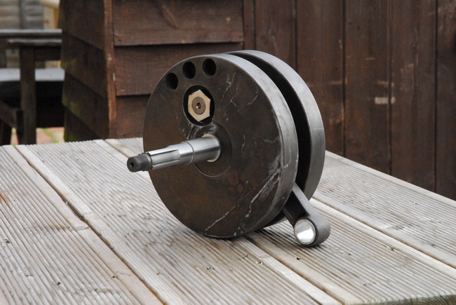
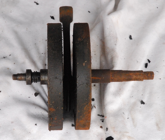 The crankshaft was another concern. The drive side axle wasn't good. There were a couple of options. I could split the crankshaft and replace the axle. New ones are available but I don't really have the facilities to true it all up, let alone apply the huge amounts of torque needed to do up the axle nuts. I would have to get that done professionally. Another option was to find a good, second hand one and as it happened, the guy I bought the dynamo and tank from had one for sale. It looked in better condition (in the photographs) than mine so I bought it. It cost less than a new axle and included the crankshaft timing pinion... which I also needed. That was a bonus that saved me £25. Time will tell if I've made the right choice.
Another concern was the clutch, or more to the point, the lack of one. Ideally, I'd like to use the Burman gearbox as that was the one fitted to the bike originally but most of the Burman clutch was missing and the bits that I did have weren't in the best of condition. I did, however, have what appears to be a complete AMC clutch that would have been used with the AMC gearbox with the later 500cc engine. It was while I was browsing through the Owners Club archive that I came across an old technical article detailing how to use the AMC clutch with the Burman gearbox. It just needs a 3/8" wide spacer to be turned up. Easy peasy... That may well be the way to go.
Thursday, 9th March 2017. I sometimes wonder why I ever got involved with old British iron, then I remember the good times. The replacement crankshaft turned up yesterday... not good at all. The seller described it as "A little play in the big end otherwise in very good condition." What a load of bollox. The play in the big end was monumental and all the splines on the drive side axle had been sheared off, rendering it totally scrap. As it certainly isn't as described, I've requested a return and refund.
As the barrel seems to be in better condition than I thought at first glance, I'll have a closer look at the crankshaft I've got. Maybe I was a little hasty in my decision not to use it. It could be that under all that rust, it is recoverable... The big end bearing feels tight but that could just be dirt and crud accumulated over the decades in the garage. I'll give it a good clean and see how it looks then. Memo to self... "Don't be in such a bloody hurry. The only time limit is you."
It would appear that I spoke too soon regarding the cylinder barrel. Just had a phone call from Derek at T & L Engineering. They've bored it out to +0.040" and there are still large rust pit holes in the bore. It was a bit worse than was first thought. It's not a problem mechanically, they are going to re-sleeve it, it's just a bit more expense. Nobody ever said that rebuilding old bike will make you rich.
Sunday, 12th March 2017. Having been away for a few days, clearing land and building a Gazebo, there was an email in my 'In-box' when I returned home. The seller of the crankshaft had agreed to me returning the crankshaft and refunding my payment, which is good news. I've also sold the useless (to me) dynamo. I didn't recoup all the money I paid for it but I did get a reasonable percentage of it back so not too bad.
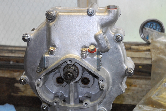
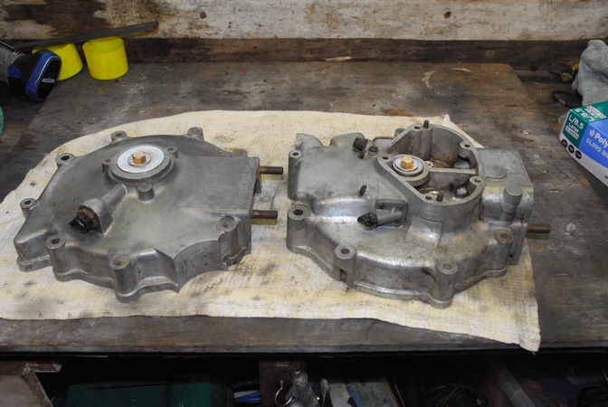 Monday, 20th March 2017. Some more progress has been made. The two crankcase halves seem to be in very good condition, considering the state of the rest on the bit's I've acquired. There is very little corrosion and no cracks or holes. That is good news. The threaded holes for the drain plug, oil pipe connections, oil pump end plates and timing cover screws are all good (once I'd run taps into them to clean out all the crap that had accumulated over the years). There are no stripped or crossed threads; that's a great deal better than I expected. I've offered up the crankshaft to the timing side main bearing bush and the fit is perfect. More good news, the bush won't need to be replaced. The bore for the oil pump plunger was dirty but once I'd carefully cleaned it up, there's no scoring showing in the bore and the pump plunger was a smooth, close fit. The gear teeth on the plunger are showing a little wear as is to be expected but they're completely serviceable and I won't need to replace the plunger. The oil pump end plates are both OK but I will use new screws and bolts when I re-assemble everything. The recess for the two drive side main bearing ball races is very good... no scoring and corrosion free. The cylinder base studs are rusty but perfectly serviceable with good threads. All in all, I'm very happy with the crankcase.
I've blanked off all the bearing holes with large washers and fitted the oil pump end caps with the old screws. I've put blanking plugs in the oil pipe connections and the drain plug. This will protect the threads and bearing surfaces when I get the cases vapour blasted.
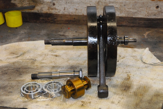 And so to the crankshaft. After buying a 'duff' one on eBay and then having to return it for a refund, I've decided to take the plunge (into my bank account) and have the one I've got rebuilt. I've cleaned it up as best I can but it's not in tip-top condition. The drive side axle is worn and rusty so I've sourced a new one (and the retaining nut) from Andrew Engineering Ltd. The timing side axle is much better... that was protected by a layer of oily crud and is perfectly serviceable. The big-end wasn't so lucky. Once I'd got some of the muck clear, it was free to rotate but it's obviously going to need replacing. There's not a lot of play and it would be OK if it wasn't for the very gritty feel. The rollers and crank pin are probably as rusty as the rest of it. I've bought a new crank pin assembly and a pair of drive side main bearings from AMOC Spares. The crank pin was not cheap!! Back in the day, I bought a complete second hand Matchless G9 for 1/10th of what the crank pin has cost me today... Ho hum!
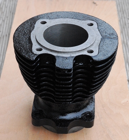 Tuesday, 28th March, 2017 I've been making rapid progress... slowly. The cylinder barrel has been re-sleeved, bored and honed back to the 'STD' 69mm diameter. The cylinder head mating face has been skimmed to remove the rust pitting and it's been given a coat of gloss black high temperature engine paint. I think it looks rather nice... A lot better than it did in the picture up the page a ways.
The crankshaft is currently with T & L Engineering having the new crank pin assembly and drive side axle fitted. I'm expecting them to 'phone me any day now to say that it's ready to be collected. In the meantime, I've been looking at the cylinder head. Structurally, it looks like it's in pretty good nick. The alloy casting is dirty and there is a little surface corrosion but nothing that a going over with a vapour blaster won't sort out. Of more concern are the cast iron valve seat inserts and the cast iron valve guides. They have suffered from rust. I've ordered a pair of new valves and valve guides. Once I've had the head cleaned, I'll drift out the old guides and install the new ones. That done, I'll re-cut the valve seats and lap in the new valves. One thing leads to another... as it always seems to with these old ladies. The new guides are the 'latest' variant and fitted with a circlip to locate them correctly in the cylinder head (the older ones have no circlip) which means that the valve spring seats which locate over the guides need to be relieved to give clearance for the circlip. Not easy as they are hardened. I could hack at them with a grinding wheel on the Dremel but there are a set of later spring seats currently for auction on eBay. They are already relieved for the circlip so if the price doesn't go too high, I'll try to win them. That will sort out the problem nicely.
 I've splashed a bit more of my hard earned pension on a pair of new pushrod tubes. The old ones were ok but the chrome plating was completely shot and they would look really rubbish up against the newly painted cylinder barrel. The new ones are polished stainless steel and look the business. Being stainless, hopefully they'll stay that way. It was cheaper to buy the new ones than to have the old ones stripped, polished and re-chromed.
Thursday, 30th March, 2017 I've collected the re-built crankshaft from T & L Engineering and dropped off the crankcase halves and cylinder head for vapour blasting. They should be ready sometime next week. We discussed valve guides and the preferred option, assuming I was going to replace them... which I am, was for T & L to remove them prior to doing the vapour blasting so that's what was agreed. It'll save me a job anyway.
 It's a case of one step forward and three back. As I mentioned previously, the Burman gearbox that I have is the one that was fitted originally to the bike at the factory so it would be nice to use that one if I can. The trouble is... it doesn't work. It's seized and the shafts don't rotate. The AMC gearbox, on the other hand, does work. Well, the input and output shafts do actually go round. It was time to fetch the Burman box up from the garage and have a look at it. I gave it a good going over with a stiff brush and a tin of white spirit to remove all the crud on the outside. It was then that I noticed the first problem. The outer cover was cracked. A previous owner had attempted to repair it with what looked like Araldite. That cover was scrap... not a particularly good start. Fortunately, Burman boxes were used on a lot of different bikes from Ariel to Vincent so there are a lot of bits about. It didn't take me long to find a good cover and the vendor accepted my offer of twenty fine British quids for it.
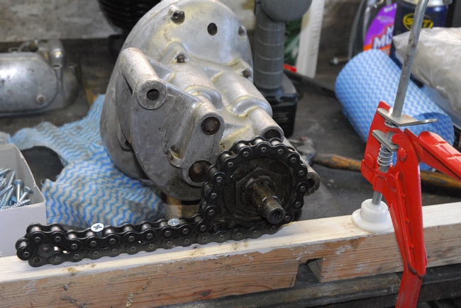 That sorted, the next job was to undo the nut that was holding the final drive sprocket. I had to hold the sprocket so I employed the same technique that I'd used on the two Triumphs... namely, wrap a length of chain around it and screw the chain to a lump of timber. That certainly stopped the sprocket from turning but could I undo the nut... could I hell! There was no way that nut was coming undone. In the end, I drilled two holes through the nut, opposite each other and effectively split the nut in half. A little tap with a small cold chisel and the nut fell off in two pieces. Result!! The sprocket was drawn off the output shaft with a small, three leg 'puller'. The sprocket is in good condition and has the correct number of teeth (16) so I'll reuse it. The oil seal behind the sprocket was no good, it hadn't been installed correctly and was badly distorted. It has to come out in order for me to change the mainshaft ball bearing behind so it's of no great consequence.
Time to look at the other end of the box, now. The gear indicator (that rusty lump where the cover is cracked) has to come off in order for me to remove the outer cover. Looking at the nut that secures it, I didn't rate my chances of getting it off easily... and I was right. I daren't put too much pressure on the nut as it's screwed onto the the gear selector drum shaft and I couldn't afford to have that shear off. I opted for surgery and used a fine cutting disc on the Dremel to slice through the nut each side of the shaft. The nut came off in four pieces with no damage at all to the shaft or thread. The gear indicator cup and the spring under it both popped off easily and will be replaced when the time comes (assuming the gearbox isn't totally scrap).
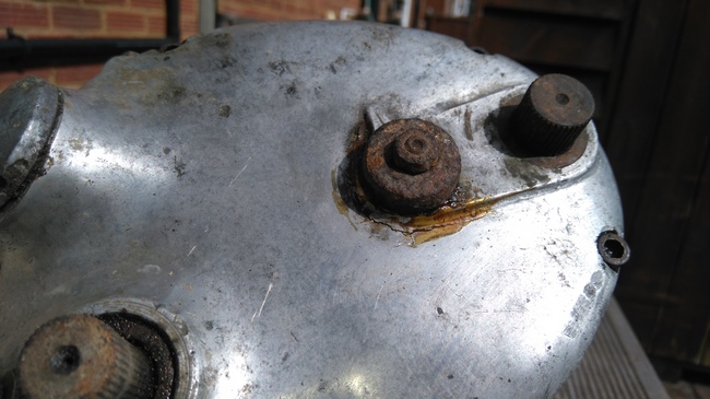
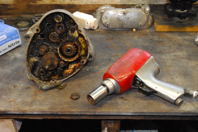
 A previous keeper had, for reasons best known only to him, replaced the 5 cover screws with hexagon socket 'Allen' screws... the black, high tensile steel variety, not the more usual stainless screws. I just knew this was going to be yet another struggle. Two of the five came out easily, the other three didn't. The heads had rusted and corroded into the the counterbores in the aluminium cover. The hex socket rounded out before they showed any sign of unscrewing. The heads would have to be drilled out. Ho hum... drilling the heads off high tensile Allen bolts is not something to be undertaken lightly as normal high speed steel drill bits will burn out very quickly. Fortunately, when I visited the bike show at the N.E.C. last year I bought a set of carbide tipped drills that the manufacturers claimed would would drill through anything. They didn't come out totally unscathed and their lifetime guarantee will shortly be put to the test but I did manage to remove the heads of the three screws. [EDIT... The damaged drills were replaced free of charge and without any quibbling.] That was just the start... getting the cover off took me the best part of an hour of 'gentle' persuasion. Oh dear... or words to that effect... It doesn't look at all pleasant. A mixture of old oil, water and rust. I'm hoping it's not really as bad as it looks and that at least some of the parts will be recoverable. The ball bearings, obviously, will be replaced and the various springs, too but hopefully the major components will clean up and the rust is only on the surface... Let's hope the pot is half full and not half empty!
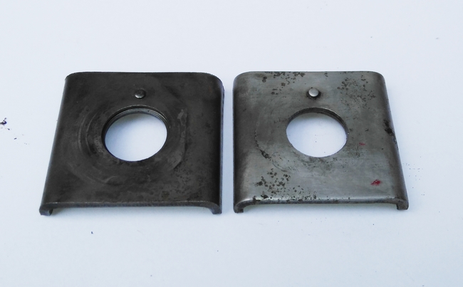 Saturday, 1st April 2017. Going back to the valve spring seats that I mentioned earlier. The early ones that were with the 350cc engine bits aren't recessed for the later valve guide circlips that I'll be fitting in due course. However, looking at photographs of all the bits I've got, I noticed that the later 500cc cylinder head that was included with the bits I bought from Malcolm had one valve spring seat fitted. Off I trotted to the garage, dug out the 500cc head and sure enough, there was one of the later version recessed spring seats. Well if there was one, then it stands to reason that there should be another lurking about somewhere... A few minutes shoogling in the heap of boxes and I unearthed the other one. Good news... I now have a pair of the later version spring seats. If fact, I had them all along, I just didn't know it. That will save me a few of our splendid British quids. OK... these were fitted to a '60 500cc engine but the 350cc and 500cc engines had the same valve gear for pretty much their entire production run so they'll fit the smaller engine no trouble at all. You can see the difference in the photo. The later version with the recess is on the left, the early version on the right.
 Tuesday, 4th April 2017. I can't put it off any longer... I have to start sorting out the Burman gearbox. Having taken the front cover off a few days ago and seen the mess inside, it wasn't a task I was looking forward too. The replacement front cover had turned up and that looked to be in perfect condition. I cleaned it up and gave it a going over with some 'wet & dry' to remove the oxidation. It will get the polishing treatment next time I set up the buffing wheel.
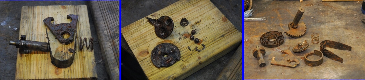
Fortunately, the old front cover dismantled easily. The kickstart quadrant, clutch release mechanism and gear change fork all came apart without a problem and after a clean up session in the white spirit tank, they didn't actually look too bad. OK... there is some surface rust and a couple of the smaller parts (springs, steel balls etc.) will have to be replaced but the major components look in surprisingly good condition. They'll get a week of soaking in my secret rust removing solution (1:4 - molasses : water - yes, really!!) followed by a going over with the wire brush. They'll be as good as new-ish.
 I had a quick look at the three screws holding the inner cover to the main gearbox case. These too had been replaced with black, high tensile 'Allen' screws and I really didn't relish the thought that these may have to be drilled out like the outer cover screws. Happily, what little oil there was had prevented too much corrosion and all three turned without drama. That left the hexagon nut holding the kickstart ratchet onto the end of the main-shaft. It showed evidence of having been attacked with a cold chisel at some time in the past and I wasn't overly optimistic about my chances of getting it off without a lot of aggravation. Once I'd cleaned it up a little, the hexagon looked in good shape and I had a socket that fitted perfectly. So I hit it with the air impact wrench, cranked up to 150 p.s.i. After a little reluctance, the nut unscrewed and I breathed a sigh of relief. Maybe the box is going to give up without too much of a fight, after all. That just leaves the selector rods to be 'disconnected' from the selector drum and the drum to be removed. It seems loose enough so I'm not expecting much trouble. Then I can take the inner cover away from the main case and get my first look at the gears and bearings... oh joy!
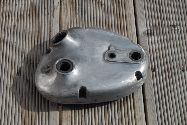
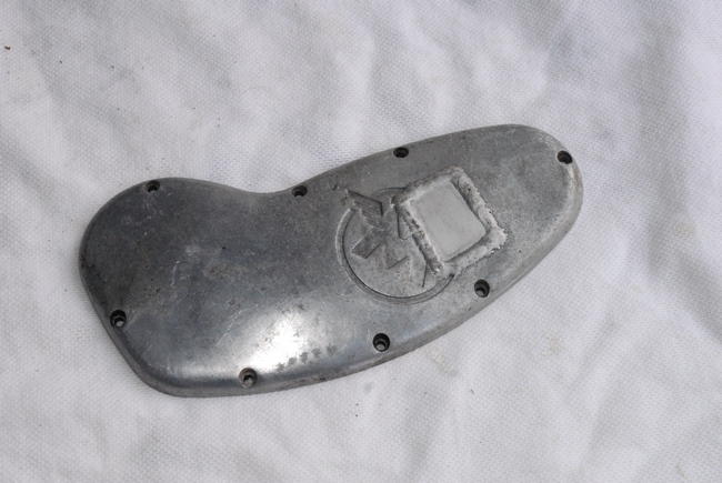 Wednesday, 5th April 2017. One of the 350cc engine parts that I'd acquired from Malcolm was the cover for the magneto drive chain... but it had been damaged at some time in the past. It had been repaired... an aluminium patch had been welded into it, presumably to repair a hole or substantial crack. OK... it was sound enough and would do the job but it just didn't look good. I'd been looking around the internet for a replacement but I'd had no luck so I placed a "Wanted" advertisement on the AMOC forum. Within 24 hours, a gentleman emailed me with a couple of photographs of a timing cover he no longer required and offered to sell it to me for a reasonable price. It was exactly what I wanted so the deal was done. Hopefully, it'll be here with me in a day or two.
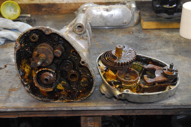
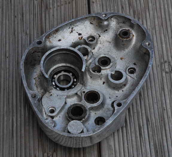
Friday, 7th April 2017. The replacement timing cover arrived this morning. It's exactly what's needed so that's another little problem solved. It was time to carry on with the gearbox. Having removed the split pins and the selector rod drive pins, the selector drum came away easily.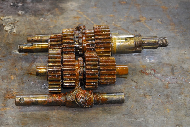 The three inner cover screws I'd loosened earlier came out OK. A gentle tap on the end of the input shaft with a soft faced hammer to break the seal and the inner cover came away from the main case. What a mess...!! The gear cluster came out in one lump and to be honest, it didn't look too good. I put that aside for the moment and wiped all the muck out of the main case. Then it was some serious washing with white spirit and a stiff brush. The case actually cleaned up rather well. The circlip holding the main bearing and oil seal was a little problematic but it had probably been in place for 63 years. It did come out eventually and in good shape, which is fortunate because it'll have to go back in when the new bearing and seal are fitted as I can't locate a new one. With the circlip out of the way, the case went in the oven at 200°C (Gas Mark 6) for 20 minutes. The bearing and seal then tapped out easily. The inner cover was treated the same way and the smaller bearing came out too. Both bearings were rusted solid and will certainly be replaced.
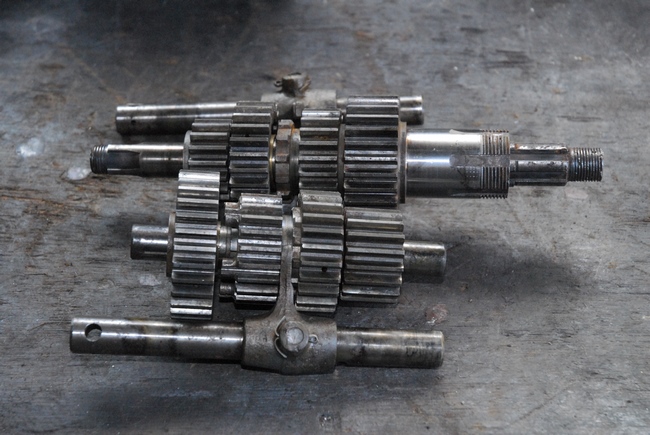 All the other components were then cleaned in white spirit, dried and given a going over with a wire brush. They are in surprisingly good nick, considering the state they were in. The gears are all in good shape with no damage other than a little surface rust and the plain bearings are a good, close fit on their respective shafts. The only parts that I think will need replacing are the ball races, oil seal, all of the fine wire springs and the steel balls in the clutch release mechanism. I'll replace the nuts, washers and the various split pins as a matter of course. All in all, it's a lot better than I expected.
Tuesday, 11th April 2017. I collected the crankcase and cylinder head from T & L Engineering yesterday afternoon. They look a lot cleaner now after being vapour blasted and washed. It was time to start re-assembling the engine. It's always a bit of a landmark time when you start putting stuff back together instead of taking it apart. First, the crankcases needed checking and making sure that all the glass micro-beads that were used in the vapour blasting were out of all the nooks, crannies and oil ways. All the passages and drill-ways were meticulously cleaned with aerosol solvent brake cleaner and then blown through with high pressure compressed air.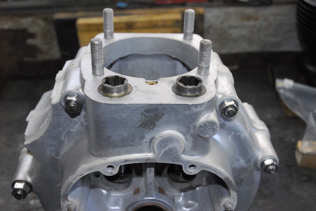 Once I was happy, the two crankcase halves were bolted together in preparation for installing new cam followers and cam follower bushes. They are a 'shrink' fit and the crankcase needed to be heated to around 200°C in the oven. (Probably just as well my wife ran off with the gypsies some time ago). The bushes had been in the freezer overnight and were down at around -14°C. The bench had been cleared and everything I needed was to hand as speed was going to be of the essence. The hot crankcase was placed on the bench and the first cam follower bush offered up (remembering to put the cam follower in first as they won't go in after the bush has been installed). With a bit of sizzling, it slid into position... almost. With about 1/8" inch to go, it stuck as the bush warmed up and the case cooled down. A couple of sharp taps with a hammer and a brass drift saw it correctly positioned, flush with the top face of the crankcase. The same happened to the second bush but again, a sharp tap with the hammer saw it positioned correctly, too. So far, so good!
While the crankcase cooled down, it was time to look at putting the drive side main bearing ball races onto the crankshaft. This proved to be remarkably easy and stress free... hooray! 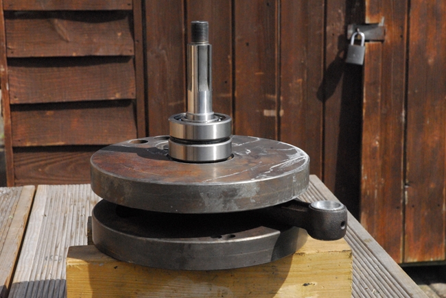 The two new ball races were placed on a baking tray and put into the oven... yep, 200°C again. The crankshaft was supported on wooden blocks on the table outside. The first hot ball race was dropped over the drive side axle and down to the locating shoulder. The washer and spacer that go between the two bearings were dropped on next, followed by the second hot bearing. No persuasion needed, they just dropped into position easily. While all this was happening, the crankcase had cooled down enough to handle so it was unbolted and the two halves separated again. Time for the drive side half to go back into the oven. By the time it was back up to 200°C, the bearings on the crankshaft had cooled down so it was simply a case of dropping the crankcase half over the bearings. It dropped on with a satisfying 'ding' and that was that... drive side main bearings installed.
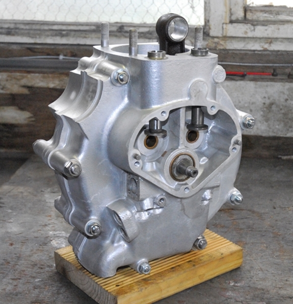
Now it just remained to bolt the two crankcase halves together. I've got a full set of new studs and nuts for the crankcase but as most of them also go through various parts of the frame and engine plates, I've made up some temporary studs from threaded rod.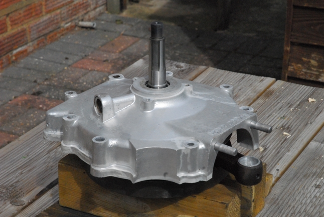 These will hold the crankcase together until the time comes to put the engine in a frame. The joint faces were painted (literally) with a thin coating of 'ThreeBond' gasket sealer. The timing side main bearing was liberally coated with 'Graphogen' colloidal graphite paste. That will keep it lubricated when the engine is initially started until the oil has had time to circulate. The timing side case was positioned over the crankshaft, the top faces of the two halves aligned and the cases bolted together. Job done... It's starting to look more like an engine now and less like a box load of old junk!
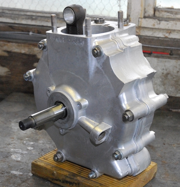
Thursday, 13th April 2017. For one reason or another, I didn't have a lot of time to play with the G3 today but I did manage to fit the piston and cylinder barrel to the crankcase. The new piston rings were placed in the cylinder bore and the end gaps checked. The manual states that it should be 0.003" - 0.004" per inch of cylinder bore. As the bore is 69mm, that works out at an end gap of 0.008" - 0.011". All the rings were within that band so they were installed carefully onto the new piston. 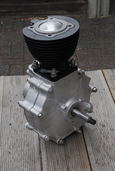 The gudgeon pin and small end bearing were lubricated with 'Graphogen' and the piston fitted onto the the connecting rod. The new circlips ensured that the pin remained in place.
A new gasket was given a light coating of 'Hylomar' gasket cement and positioned on the cylinder base joint face. The cylinder was then positioned over the piston, ensuring that the rings were compressed into their groves. I eased the cylinder down onto the crankcase and bolted it all up with new, stainless steel, double hexagon nuts. Not at all sure why double hex nuts are specified but they are, so I used them. The last thing I did today was fit the new timing pinion to the crankshaft... remembering that the securing nut has a left hand thread. Apart from putting the oil pump back together and putting new blanking plugs in the oil passages, that's all I'll be doing to the the engine for now. I'll put the cylinder head on once the engine has been installed in whatever frame I can come up with. The head has been vapour blasted and looks good. I have the two new valve guides to fit and then I can re-cut the valve seats, install the new valves and it will be ready to bolt on when the time comes.
I've got most of the new parts I need to re-assemble the gearbox now. All I'm waiting for is the large nut that holds the final drive sprocket. Draganfly Motorcycles have emailed to say it's been despatched and should be here in a day or two so that will be the next task. Hopefully, it will all go back together without any major hitches and I'll have a fully functioning transmission. Watch this space!!
 Easter Monday, 17th April, 2017. Having spent an enjoyable few days away in deepest Surrey witnessing my ex-wife's "Handfasting" ceremony with her new partner, it was time to get back to doing some more on the Matchless. Not that I actually did very much today. The oil pump plunger was cleaned, lubricated and slipped back into the crankcase. The old locating pin showed no sign of wear so it was re-used with a new screw. [EDIT IMPORTANT... After receiving a phone call from Ken DeGroome, the fibre washer has been removed from under the guide pin retaining screw. Apparently, this reduces the engagement of the guide pin in the pump plunger and can lead to excessive wear and ultimately catastrophic failure.] With that securely in position, I turned the crankshaft over a few times to ensure that the plunger moved in the approved manner... it did so I sorted out the end caps. Hmmm... after cleaning the 'return side' end cap I found that it was cracked. I'd had enough problems with the AJS M18 oil pump sucking air so there was no way I putting a cracked end plate back on. I'd got another 500cc 'bottom end' in the garage and a quick check revealed a good end cap on that so it was liberated for service on the G3. A thin smear of Hylomar on the paper gaskets and the two end caps were screwed into position with new screws on the feed side and bolts on the return side... as per original assembly.
The old oil-way blanking screws had seen better days so I've put three new stainless ones in with new red fibre washers. A new stainless crankcase drain plug was screwed in and a new breather valve diaphragm installed. That was about it as far as the engine goes for the moment. I've got that safely stored away in the spare bedroom... I did spend an hour or so cleaning up the last of the gearbox components ready to put that back together again.
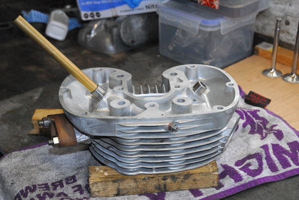 Tuesday, 18th April, 2017. This morning, I set up the buffing wheel on the bench grinder and cleaned up a cover or two. Specifically, the gearbox outer cover and the magneto drive chain cover. They're not perfect... 60 years of abuse has left them with some dings and scratches that would need more than a buffing wheel to remove but I'm happy with the result. It's fair wear and tear and it qualifies as 'patina'. That accomplished, it was a quick trip over to my sister's house to avail myself of the brother-in-law's Myford lathe. I'd acquired a length of 1/2" diameter brass bar and needed to turn one end down to 3/8" diameter. That would serve as a drift when I install the new valve guides later. I also took the opportunity to use the lathe to drill and tap a 3/8" BSF hole through the centre of a 50mm diameter x 10mm thick steel disk. I have no use for that at the moment but it will become part of a tool to disassemble the front fork legs in due course.
Back home again, the cylinder head was popped into the oven at 200°C for twenty minutes... Sound more like a Delia Smith recipe, doesn't it! The new valve guides have been in the freezer for a couple of days so I was all set to install them into the head. 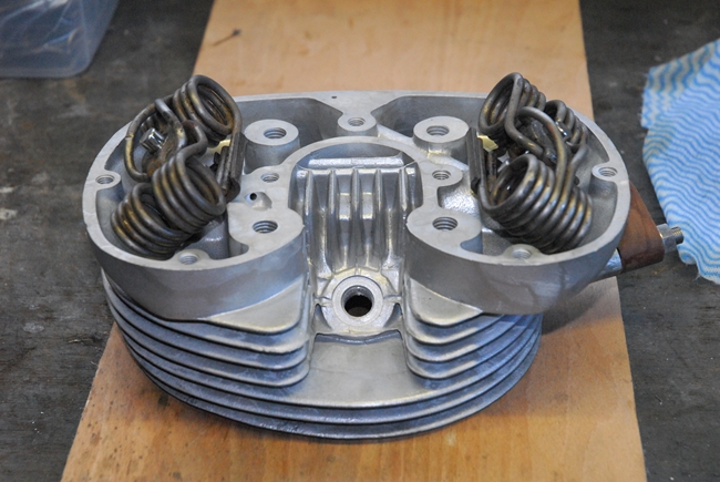 It's important that the valve guides are orientated correctly so that the oil feed holes in the guide line up with the drill-ways in the head. They sizzled a bit but needed little persuasion to get the circlips seating nicely against the head. At that point, I left the head to cool down and collected together the two new valves, the springs, valve caps and split collets.
The new valve guides went in pretty much perfectly aligned with the valve seats. They were that good, I didn't even bother to re-cut them. They weren't pitted anyway and just a lick or two with fine grinding paste brought up a smooth, grey, even seat all the way around. I'm very happy with that. Then it was a job I wasn't looking forward to. I've never fitted hairpin valve springs before but how hard could it be? Well, I'll tell you. I struggled with the first one. I had to take the angle grinder to my valve spring compressor and reduce the width of one of the 'arms' so that it would fit inside the narrower of the two springs. It was fiddly but after about 20 minutes I'd got the inlet valve installed. Having got 'the hang' of it, the exhaust valve went in much more quickly. Man... there's a lot of energy wound up in those springs. [EDIT... I have since learned that the springs are much easier to replace if you use the correct procedure and tools.]
Thursday, 20th April 2017. I had a bit of a struggle today. As I seem to be working my way up the engine from the bottom and finished the cylinder head last session, today it was the turn of the rocker box. Like all the other components I've got, the aluminium casting hadn't coped well with being neglected for 30 years. It had some surface corrosion but was basically sound. There was nothing that a little vapour blasting wouldn't sort out... If I could dismantle it.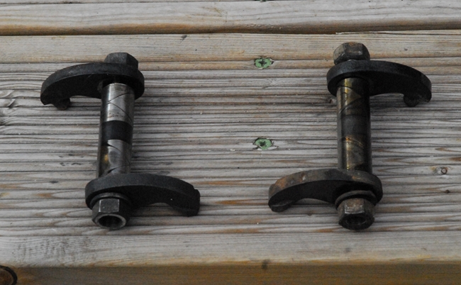 On the face of it, a simple enough task. The rocker shafts run in bronze bushes in the aluminium casting. The rocker arms are secured to the rocker shafts with nuts. To dismantle it, the nuts on the inside of the casting need to be removed and the valve arms taken off in order for the shafts with the pushrod arms to be withdrawn through the tappet adjusting aperture. Still with me? The struggle started when I realised that there was no way I was going to get a ring spanner on the inside nut and an open ended spanner only had limited movement... and the nuts were bloody tight. In fact, I snapped the jaw off a chrome vanadium spanner trying to get them undone. A few minutes with a propane torch and I managed to get the nut on the inlet rocker loosened and subsequently removed that rocker assembly. The nut on the exhaust rocker stubbornly refused to budge. Then I had one of those 'light bulb' moments. If I loosened the nut at the other end of the shaft, maybe it would release the pressure on the one I had to remove and I would be able to get it undone... and that nut I could get at with the air impact wrench. A couple of minutes later and that nut was undone, the shaft tapped through towards the stubborn nut and I got that undone as well. Yippee.... With both rocker shafts out of the way, I could clean all the old oil and muck out. The rocker box has been duly sent off for vapour blasting and will be returned to me in due course. In the meantime, I can clean the surface rust off the rocker arms and check the contact faces for wear.
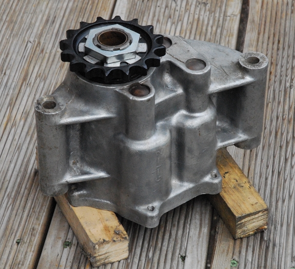
 With the rocker box put to one side for the moment, it was back to the gearbox. I had all the new parts that I needed; bearings, a few springs, lock washers and nuts and a new selector drum detent plunger. First job was to install the output sleeve ball race and oil seal. That followed the usual method of heating the case, cooling the bearing and putting the two together. The new oil seal had already been pressed into the seal carrier ring and that assembly dropped into the case. The whole lot was secured with a circlip. No stress there; it all went back together easily. The spacer and final drive sprocket were slipped over the output sleeve and secured with an new tab washer and a new nut.
 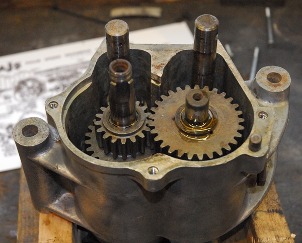 At this stage, it's only "finger tight" as I'm awaiting the delivery of a new 1" Whitworth socket with which to finally tighten it. I never object to buying tools that I don't have... If I have a particular need for them. The same method was used to install the smaller ball bearing in the gearbox inner cover.
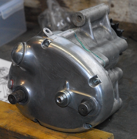
Saturday, 22nd April, 2017. The 1" Whitworth socket has arrived so the sprocket nut was fully tightened with the air impact wrench and two of the locking washer tabs bent up on opposite 'flats' to secure it. Right... time to build up the gearbox. The mainshaft, with all the gears assembled onto it and the selector fork in place was first to go in. Then the layshaft was installed, the gears and the second selector fork built up onto it. Splendid... that all went together easily. The gears mesh and turn as they should. The inner cover was next. The bearings lubricated, a smear of Hylomar on the gasket and the cover installed. I used the same three inner cover screws that were in there originally as they were OK and undamaged. So far, so good. The kick-start gear and ratchet were positioned on the end of the mainshaft with a new spring and a new nut. You certainly don't want this nut to come loose so a little blue 'Loctite 242' was applied to the thread before the nut was put on. 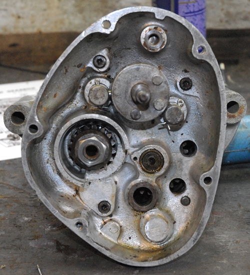 The original selector drum detent plunger was badly rusted and the spring broken so I'd obtained new ones. The locating hole in the cover was cleaned and lubricated, the spring and plunger installed. That moved nice a freely. Then came the tricky bit... It should have been an easy task to fit the selector drum; well actually, fitting the selector drum was easy, it was connecting the selector rods that was the tricky bit. There is a short rod that goes through a hole in the end of each selector rod and locates into a groove in the selector drum. The short rod is secured in the selector rod with a split pin. Could I get the holes to line up and the split pin through? In a word... No... It took half an hour of fiddling about before they finally gave up and allowed me to fit them. With that finally accomplished, the next bits were easy. The gear change quadrant was fitted over the selector drum with a new spring and oil seal. The clutch release mechanism was assembled with three new 5/16" diameter steel balls and a new spring. That was located in the outer cover as was the kick-start quadrant with the original spring and the gear shift spring. The gasket was fitted with a smear of Hylomar and the outer cover tapped into position. That was secured with five new screws to replace the ones I'd had to drill out and that was just about it. There was only the new gear indicator to fit. It's currently secured with an ordinary nut but I have a dome nut on order that will look better. Hopefully, I've got a fully working gearbox. I can't check the gear change operation at the moment as I don't have a gear shift lever but I'm confident that it's all gone back together correctly.
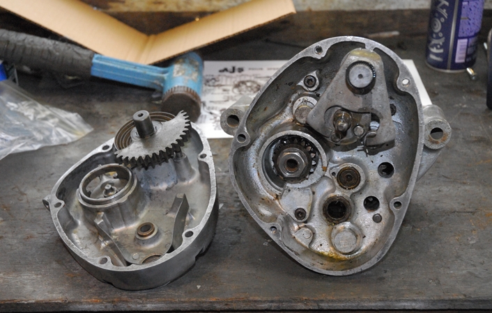
Friday, 28th April, 2017. The rocker box came back from the vapour blasters yesterday so all I had to do today was assemble the rockers into the box. I'd recently had a problem with the 500cc AJS where the nut holding the inlet pushrod rocker arm worked loose and dropped off. That caused a considerable clattering from the engine and not something I wanted to happen on this engine so all new nuts were used. 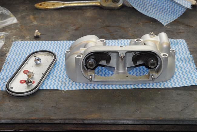 They were secured with a drop of blue Loctite and tightened with the air impact wrench. The bearing sleeves were given a coating of Graphogen to keep them sweet until the oil started circulating. Three new studs for the tappet cover were screwed in and I'd bought three new chrome plated knurled nuts as well.
That's really about it for the engine and gearbox until it's installed in whatever frame I can come up with. I don't want to put the cylinder head on until after it's in the frame as it makes the engine easier to handle and allows me to accurately set up the ignition timing with a dial test indicator on the piston. Talking of ignition... I sorted out the magneto from the boxes of bits that are still in the garage. It's a Lucas N1 magneto, if anyone's interested. I expected it to be in the same dubious condition as everything else and in some respects I was right as the points housing was badly corroded and I couldn't get a spark out of it but it certainly wasn't beyond repair. That was the good news. Dave Lindsley was my first choice for reconditioning so I gave him a call. Yes, he could do it but he was fully committed for work until the end of October and the cost would be getting on for 400 of my hard earned pension quids. Bummer. My second choice was The Magneto Guys but like Dave Lindsley, they were fully committed and weren't taking on any work at all for the next few months. There must be a hell of a lot of broken magnetos out there somewhere. 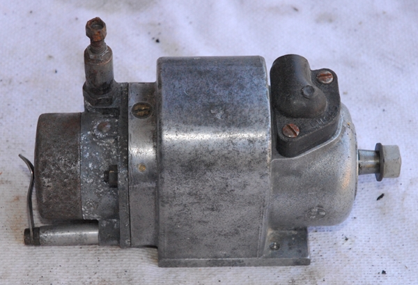 Right... Time for 'Plan B'. I phoned the AMOC Spares. Yes, they did reconditioned magnetos on an exchange basis and they had the N1 type in stock. Splendid. A relatively quick blast up the M1 to Northampton and then the A45/A43 to Kettering and I pitched up in the AMOC Spares retail outlet. Then I hit a snag... The guy behind the counter was obviously having a bad day. He pointed out that the points housing was corroded. I replied that I thought that was the idea of service exchange.... I give you an unserviceable magneto and a fistful of wedge and you give me a reconditioned magneto. "But the more bits we have to replace, the more it costs us." was his reply "and anyway, this is for a 500cc bike and we haven't got any of them in stock. We've only got the 350cc ones." Now that confused me a little because I thought that both engines used the same magneto. I asked what the difference was. According to him, the points housing has the advance cable entry on the other side. "No problem... It's going on a 350cc engine anyway so I'll have one of them, please." That wasn't going to happen because they only exchange units on a 'like for like' basis and he couldn't possibly swap a 500cc magneto for a 350cc magneto. I did point out that if the points housing was the only difference, it going to be replaced anyway so it could be replaced with the 350cc version.
 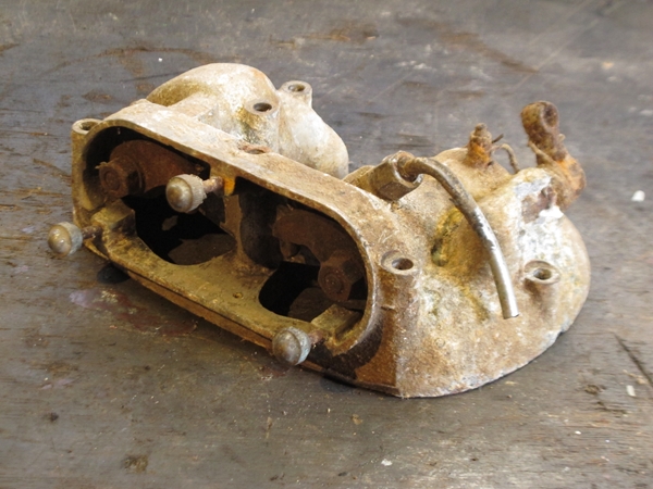 That way the 'status quo' would be restored and all would be well in his world. Still wasn't going to happen and there was no way I was going to walk out with a 350cc magneto so we reached some sort of compromise. I left my magneto with him to send away to be reconditioned and they would let me know when it was ready. Ho hum....
Tuesday, 2nd May, 2017. Work started this morning at the crack of 10 o'clock with me shoogling about in the garage looking for the scrap rocker box that was in one of the boxes of bits. There was an exhaust valve lifter lever in it that might just be salvageable. I found the rocker box but the valve lifter lever really looked too far gone to be of any use, even if I could get it loose from the corroded aluminium. In the end, that idea was abandoned. I did strip out the rocker assemblies as they may well be useful at some time. The aluminium casting was put back in the garage but I might just as well have chucked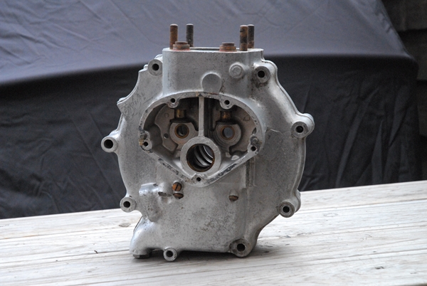 it in the recycling bin as it will never be used on a bike again. On to the next job... I'm getting close to starting on the frame. Before I send anything away for powder coating, I'd like to at least get an idea of which bits I'll be using and which bits are surplus to requirements. I don't really want to be lugging the engine about while I'm sorting out the chassis but I do need to have it in place to check that I've got the correct engine plates and that the transmission fits and lines up correctly. What I need is a 'dummy engine'; and as it happens, I have a spare 500cc bottom end sitting in the garage. At least, it was... now it's in the shed. I've stripped off all the timing gear, split the cases and removed the crankshaft. That just left the empty cases which I gave a good going over with Gunk and hit with the pressure washer. As it's basically the same as the rebuilt 350cc engine, I can use that when I 'mock up' the rolling chassis and just drop the 350cc engine in when the time comes.
Thursday, 5th May, 2017. Those of you that have been paying attention will remember that back on the 18th April, I used my broth-in-law's lathe to drill and tap a hole in a steel disc that was to become part of a tool for dismantling the front forks. That tool has been finished and today was the day to see if it worked.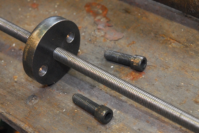 The front fork legs had already been partially dismantled in as much as they had been separated from the top and bottom steering head yokes. On the face of it, the main parts didn't look to have suffered as much as some of the other parts in the garage. The stanchions had some surface rust but they were straight but there was no serious surface pitting in the places that matter. The aluminium sliders had some corrosion but I'm sure they'll clean up and polish reasonably well. The studs for securing the end caps were very rusty and need to be replaced so they were unscrewed from the bottom of the slider and discarded. One stud was very loose and it looks like I may need to repair that thread with a Heli-Coil insert. There was no discernable looseness or play in the bushes so it all looked good but I did need to get the old oil seal out as it would have gone hard and useless over the years of storage. That's where the fun started. Unscrewing the chrome plated slider extensions was fairly easy; the slider was held in the vice with rubber 'soft jaws' and the aluminium heated with a hot air gun to expand it a little. The extension was unscrewed using a strap wrench meant for removing oil filter canisters. The extensions have rusted beyond use so they'll be replaced with new polished stainless items. So far, so good. That just left the oil seal and top 'Bakelite' bush that are pressed into the top of the slider.
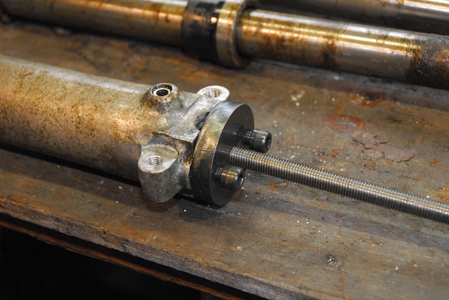 The 'conventional' way of removing the oil seal and bush, as recommended in the workshop manual, is to undo and remove the damper tube securing screw in the bottom of the slider, then hold the slider in a vice and give the stanchion a few sharp tugs. There is a flaw in that method... Inside the slider there is a short coil spring to control the fork 'rebound' and tugging on the stanchion merely compresses the coil spring. A much easier way is to bolt a plate with a threaded hole to the bottom of the fork (and I just happen to have one of those) and screw in a length of threaded rod to push the stanchion up, compress the coil spring and if you continue to screw in the rod, push out the top bush and oil seal. In practise, it worked effortlessly... but not painlessly, unfortunately. The fork slider was held in the vice, I was screwing in the threaded rod with a ratchet spanner in my right hand whilst supporting the stanchion tube with my left. Remember that compressed coil spring? When the oil seal and bush popped out, the coil spring fired them up the stanchion tube at high velocity, straight into my hand. That, I can tell you, brought a tear to my eye and a few choice words in praise of my stupidity. I revised the method somewhat for the second fork leg!!
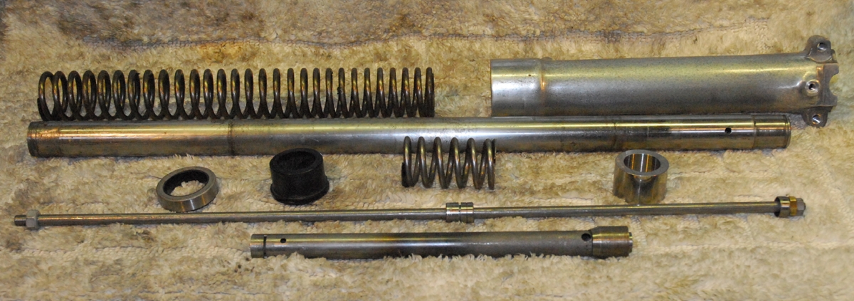
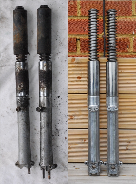 Saturday, 13th May, 2017. I finished refurbishing the front forks last week. The four studs that hold the spindle caps have been replaced and one of the threads in the aluminium for sliders has been repaired with a 5/16" BSF 'Heli-Coil' insert. I've fitted new oil seals and new polished stainless steel slider extensions to replace the very rusty old chrome plated ones. That's as far as it goes at the moment.
I collected the top and bottom yokes (triple trees if you're an American) from the garage. The top yoke wasn't in bad nick, considering. I've cleaned it up and it's perfectly serviceable. The bearing race was good as it had been protected by a liberal coating of old grease. There are no 'chatter' marks so it was removed and will be re-used after the yoke has been powder coated. The bottom yoke and steering stem was another matter entirely. It was very rusty and I wasn't at all sure I could salvage it. There were two nuts rusted onto the thread at the top of the stem, the bearing race was rusted solid to the bottom of the stem and the stanchion clamp bolts were rusted into the yoke body. Time to fire up the trusty propane torch. After getting the two nuts on the stem seriously hot, they gave up without too much of a fight. The same for the stanchion clamp bolts. It wasn't looking too bad, after all. The bearing race was having none of it, though. In the end, I cut through it as far as I could with a fine cutting disc on the Dremel and then gave it a clout with a small cold chisel. The ring broke neatly into two pieces and fell off. That's the way to do it!! I'll be going up to CWC in Coleshill next week to have the front wheel rebuilt so I'll have both yokes powder coated gloss black at the same time.
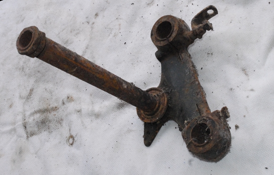 Sunday, 14th May, 2017. Time to have a look at the front wheel. The rim was rusty and the full width aluminium hub and brake plate had some light corrosion but actually, didn't look in too bad a condition. The first job was to take off the brake plate and then strip out the spindle and bearings. That proved somewhat less difficult that I'd thought it might be. All the bits unscrewed and after the hub was heated with the hot air gun, the bearing outer races tapped out easily. The bearings are taper rollers and the hardened spindle is used as the inner race. Replacements are no longer available so I was hoping that they were going to be ok. That proved to be the case. The hub was full of grease and that had protected the bearings during their time in 'storage'. They are perfect and will certainly be put back in the hub once it has been powder coated and has had a new rim spoked onto it. As I mentioned earlier, the old rim was rusty and so were the spokes, so there was not a lot of point in spending time and effort undoing all the nipples... I cut through all the spokes with a small pair of bolt cutters. A de-greasing session and a going over with a wire brush is all that was needed as this time.
The painted fork spring covers have been de-greased and given the wire brush on the angle grinder treatment. They are quite badly pitted in places and I don't think just having them powder coated will be the right thing to do as the pitting will still be evident in the surface finish. I'm going to take them (and the upper fork shrouds, headlamp shell and switch plate) over to Otto Racs (Ernie the Paint). Hopefully, I can persuade him to prepare the surfaces properly with filler and then spray them gloss black with a clear top coat. It will be a bit(?) more expensive but it will be a much better job in the end. Ho hum.... it's only money.
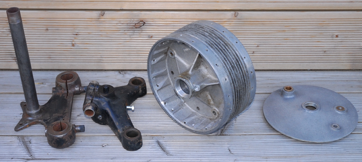
Monday, 15th May, 2017. Took a trip over to see Otto this morning. Fortunately, he was in a good mood and not exceptionally busy so he's going to do a proper paint job on the fork shrouds, headlamp shell and switch panel. Didn't get offered a mug of tea, though... bummer!! Having got the front wheel more or less sorted, it was time to have a look at the rear. 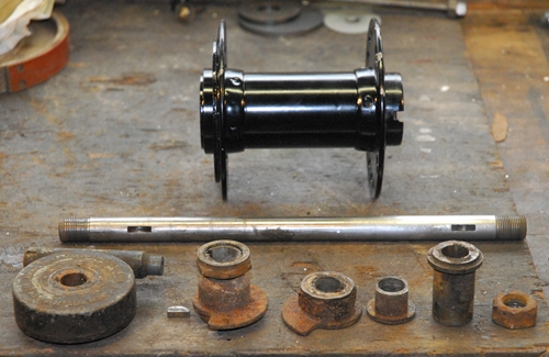 Unlike the front, the rear had already been stripped. The spool hub had been painted black and didn't look too bad at all. There are a couple of small chips in the rim but I may well just touch them in and use it as it is rather than have it all stripped off again and powder coated. The bearings, spacers, grease seals etc. had all been cleaned, identified and stored in plastic bags. Having checked them, I was pleased to find that all the parts were present and usable, although the bearing adjuster locking ring had been abused with a hammer and chisel so I'll probably replace that.
There was a spindle in one of the boxes of bits but it's for a 'swinging arm' rear end and as I'm hoping to use the rigid frame, I may well have to sort out some custom spacers. At some point in the not-too-distant future, I'll build the hub up with the brake drum and speedometer drive gearbox and offer the lot up to the frame. That way, I'll be able to see if the rigid rear end is a viable option.
Wednesday, 17th May, 2017. No work on the bike today, instead I took the front wheel hub, front brake plate and the two fork yokes up CWC to be powder coated and have a new stainless rim laced onto the hub. The purists and 'rivet counters' will point their collective fingers and mutter obscenities into their pints of mild... The front hub and brake plate are going to be gloss black instead or raw aluminium and there won't be any black paint around the centre of the rim. Why...? Because I like black hubs. It's my bike and I'll build it to suit me... so there!! Power to the people, eh, Wolfie.
Friday, 19th May, 2017. I knew things were going too well. I've had two minor setbacks in the last few days. First, I've been informed by somebody who should know, that the rigid rear sub-frame I had intended to use was for a 1949 machine and was used for that year only. Apparently, it has a 'narrow' rear fork and the rear wheel I have was intended for the wider rear sub-frame that was used from 1950 onwards. I still have to verify that so all is not yet lost. If the worst comes to pass, and the frame and wheel are incompatible, then I still have a couple of options. Find a later rear sub-frame or use the 'swinging arm' rear frame and suspension. Both options are 'doable'. Secondly... You may remember that I left my magneto with AMOC Spares to be refurbished. Well it turns out that the guy who refurbishes the magnetos has had a stroke and won't be taking any more work. Bummer... both for him and for AMOC Spares. This afternoon I drove up to Kettering to get my magneto back (and pick up some other bits while I was there). There are a couple of ways I can go, now. Find somewhere else to get the thing refurbished or fit a more modern upgrade / replacement similar to the electronic ignition systems I've got on the two Triumphs. I'll think on it some....
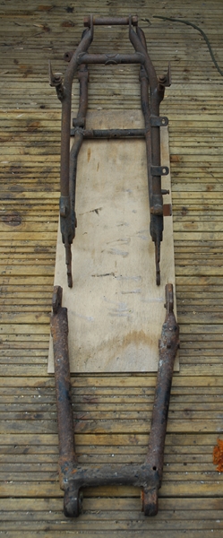 There is also a third option which I've only just thought about. I could possibly convert it to the normal coil and contact breaker system. I have all the parts that I stripped off the 500cc engine. At first glance, it looks like the timing cover from the larger engine will fit straight onto the G3 crankcase. It would mean changing the camshafts and putting the 500cc cams in the 350cc engine but as far as I can tell, they are interchangeable anyway. Of course, it would mean fitting an ignition switch somewhere but that shouldn't be an insurmountable problem and I could also convert it to a 12 volt system at the same time. Something else to think about...
Monday, 23rd May, 2017. It would seem that the guy who told me about the rigid frame not being useable was right. I fetched them both out of the garage today and the rigid rear end is a lot narrower than the swinging arm fork. That's disappointing... It looks like I'll have to build up the rear suspension after all. As I mentioned up the page aways, the swinging arm and the cast aluminium frame member that it pivots on weren't in the best of condition. The steel rear fork was very rusty and the aluminium part looked very corroded. I gave it a cursory wipe over and set about separating the two parts. That meant getting the pivot tube out of the bearings in the fork. On the face of it, it didn't look too difficult and in all honesty, it wasn't.... once I'd figured out how to do it. 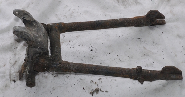 There is a cover plate on the bearing housings each side of the fork but only one of them had what looked like a screw securing it. It came undone easily enough and turned out to be a 'spoke' that ran through the centre of the bearing and secured both cover plates. With that and the two covers out of the way, it was simply a matter of pressing the steel bearing tube out of the aluminium casting. Simple... if you have a hydraulic press. I don't have so it was case of using a length of M12 studding, a piece of steel tube and a couple of 1/2" drive sockets. Screw the lot together and pull the bearing tube out. Worked for me!!
As it turned out, a previous owner had seen fit to ignore the instructions in the 'Drivers Handbook' that says the swinging arm bearings should be filled with oil and had pumped in a load of heavy grease that had never reached the bearings. Consequently, the steel bearing tube was, to put it bluntly, knackered. Fortunately, it was the steel tube that had worn and rusted, the bronze bearings were OK. I can get a new bearing tube easily and relatively cheaply. So far, so good. I attacked the aluminium casting with a wire brush and it came up surprisingly well. Certainly good enough to re-use so that will go away for powder coating in the fullness of time. The steel rear fork is quite badly rusted but I believe it will be useable once it's been media blasted to remove the rust and then powder coated. All I have to do now is find a pair of 'Jampot' rear suspension units. That may be easier said than done but I've put a few 'feelers' out and hopefully, I'll manage to locate a pair.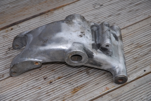
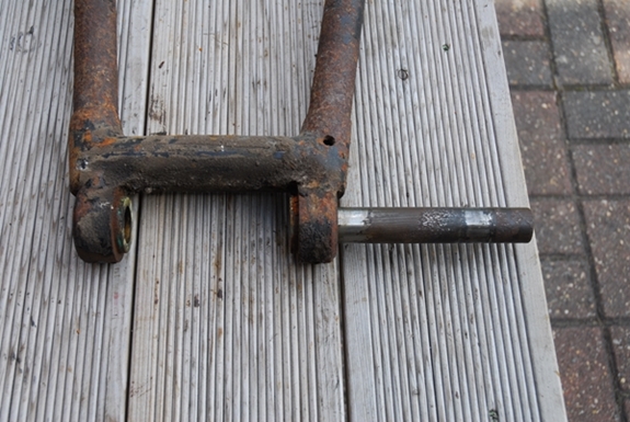
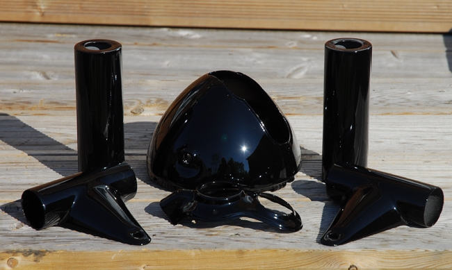
Thursday, 25th May, 2017. Ernie 'phoned yesterday morning to say that the paintwork was done so after a leisurely lunch at The Strathmore Arms, Les and I went over to collect it. As usual, Ernie has done a cracking job and the black bits for front forks look great.
Today, I felt more like a blacksmith than an engineer. I took the rigid rear end back down the garage and brought up the lower rails and rear sub-frame that I'll have to use with the swinging arm rear suspension. The pillion footrests were solidly rusted into the lower rails and they needed to be removed before the rails could be prepared for powder coating. That meant a sweaty hour with the angle grinder and drill to deal with the pivot bolts and a couple of other odd brackets that had been left attached. With all the odd brackets, nuts and bolts successfully removed from the frame components it was time to assess what I'd actually got and what I was going to do with it. The main frame is in good condition. From what I could see, it was straight and there wasn't too much rust on it. 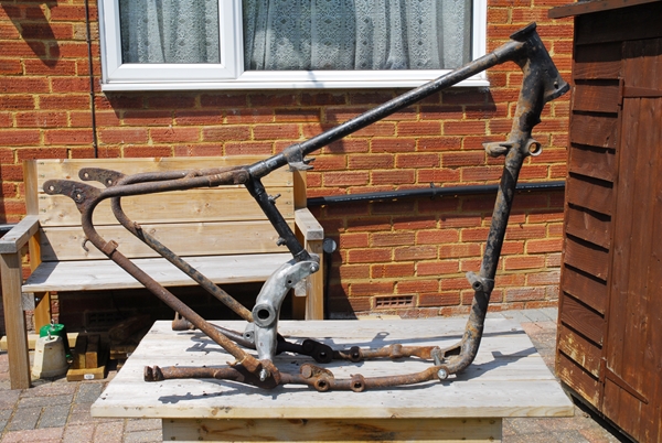 The bottom rails were somewhat rougher but once cleaned up and powder coated they would be perfectly serviceable. The rear sub-frame, however is a different kettle of fish entirely. It looks like it's been stored in a garden pond for 30 years. It's badly rusted and deeply pitted. The tubes have lost a lot of their wall thickness due to rusting, particularly, the short cross-tube at the top. I think I'll start looking for a replacement. If I can find one in reasonable condition, so much the better.
I had hoped to use the spare 500cc crankcase with the Burman gearbox to check that I'd got all the correct engine plates and other sundry bits and pieces before taking the frame up to be powder coated but unfortunately, that later model crankcase is slightly different to my 350cc engine and won't fit in the frame without a little modification and I don't really want to do that. I'll bolt in my G3 engine at some point when I've sorted out all the other parts.
Friday, 26th May, 2017. I had a phone call this afternoon from another member of the AJS & Matchless Owners Club who had seen my 'Wanted' advert for a pair of 'Jampot' rear suspension units. He had a pair (more than a pair, actually) that had been dismantled and offered them to me at a reasonable price so I gratefully accepted. Hopefully, all the parts to make a complete pair are there and I can put them back together. It would be sensible to fit new oil seals at the same time. I've never worked on these before so it will be a bit of a learning curve. Hopefully, I won't need any special tools that I can't work around... Time will tell.
Friday, 2nd June, 2017. It's news time... Some bad, some good. First the bad news. The carburettor that came with the bits isn't the right one. It looked about right when I took it apart but checking with AMAL, it was originally fitted to a BSA B31. The choke size is too small for the G3 (1" instead of the correct 1.1/16" diameter) and the float chamber is not cranked at the correct angle for the G3's downdraft (it's 7° instead of the correct 3°). All this means that I have to find a carburettor as well as all the other bits that are missing. It may be easier to find the later 'AMAL Monobloc' type as fitted to the G3 from '55 onwards.
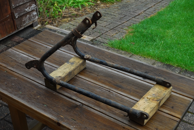 The good news is that I've sourced a replacement rear sub-frame to replace the very rusty one that I had. AMC Classic spares had one at a reasonable price so yesterday morning I went over to their place in Clifton to collect it. While the proprietor, Steve Surbey, and I were discussing old AMC machines he asked me what I was going to do with the rigid rear end that I couldn't use. He would, it transpired, be interested in acquiring it for his second hand stock. More about that later. More good news is that the "Jampot" rear suspension units arrived yesterday as well. They've obviously been around the block a few times but they are 63 years old after all. While they aren't in great shape cosmetically, all the parts are there (with a few spares) and I will be able to rebuild them with a few new parts and I'm sure they will serve their purpose admirably. I will have to fabricate some sort of spring compressor to enable me to fit the retaining circlip but I already have an idea about that up my sleeve.
This morning, I checked out just what new parts I'd need for the suspension units. The upper and lower covers are pretty well shot. The lower chrome plated ones are devoid of chrome, dented and have a lot of rust. The upper black painted covers are dented and rough. They could be recoverable if I was really strapped for cash but new ones are available and not expensive in the great scheme of things. Obviously, items like sealing washers and oil seals will be replaced as will the rubber bushes in the mounting clevises. 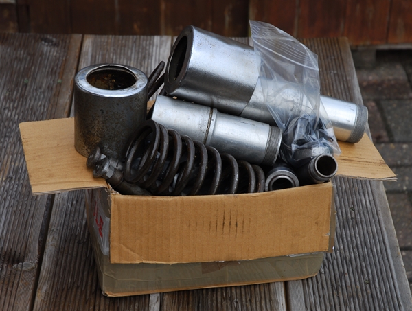 The main steel slider tubes and the hydraulic damping valves are all in good, reusable condition, fortunately. I made a list of the bits and 'phoned Steve at AMC Classic Spares again. He had most of the bits I wanted but not the new chrome lower covers and the lower cover retaining rings. I mentioned the rigid rear frame and he was happy to take that in part payment. He was also happy to take some other parts off my hands, namely the 500cc bottom end and the aluminium primary chain case so I loaded it all into the back of the car and headed off to Clifton again. Steve was happy with the bits I'd brought over and they were worth more to him than I'd expected, so a deal was done... I came away with all the Jampot bits and a not insignificant line of credit against future spares purchases. I'm well pleased. The two parts that Steve didn't have... AMOC Spares did so while I was in a driving mood and in roughly the right direction, I carried on north to Kettering and picked up the remaining bits. The new painted outer covers aren't painted all that well, just a blow over with black paint that won't last long so I'll put those with the other stuff that will be going to Ernie in the not too distant future for a proper paint job. So far... so good!
Wednesday, 21st June, 2017. Anybody who may have been foolish enough to be following this blog will have probably lost interest as it's been almost 3 weeks since it was last updated. There is a reason for that... nothing much has happened and I've been in Berlin for a few days having a break with some good friends. However... today a little progress has been made. I 'phoned a local powder coating company, Markell Ltd, that had done some work for me on the T120 project a couple of years ago. They are quite happy to take on the job of cleaning and powder coating the four major components that make up the frame for the G3. That's the main frame, the rear sub-frame and the two bottom rails. The lady I spoke to was most apologetic and said that they were extremely busy and it would be at least 7 to 10 days before it would be finished.... That is a result.... CWC are currently quoting 7 to 10 weeks!! I was told to take the frame to the side entrance and ask for "Jack". No problem there as it was Jack I dealt with last time. The parts have been loaded into the car and I'll take them up tomorrow morning. This is a turning point as the re-assembly can be started when I get the frame back and it will be more like a motorcycle and less like a garage full of old 'tat'.
Friday, 14th July, 2017. I'm beginning to wonder if I'm going to live long enough to finish this project. It seems to be taking an age to get stuff back from being painted, powder coated and having the front wheel spoked up with a new rim. I suppose that another month or two on top of the three decades it's been in bits doesn't amount to a whole hill of beans! There is some good news, though. I phoned Markell's this morning and was told that the frame had been ready since the beginning of last week. They had apparently called my mobile but couldn't get through. Ho hum... I guess the phone was 'out of service' while I was in Surrey for a wedding last week. Anyway, I collected it this morning. Given the condition it was in, they haven't done a bad job, I suppose. At least it's black and shiny.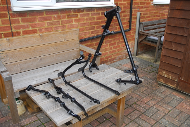 I also 'phoned CWC today and was told that my wheel was at the top of their list. The excuse they gave was that they'd "run out of stainless rims. A new delivery was expected early next week so I shouldn't have to wait too much longer." Ho hum... again! I'm having less luck with Ernie... He's not answering my messages. S'pect I'll have to go over and find out what's taking so long. I've also blown what credit I had with AMC Classic Spares. I've ordered all the studs, nuts and bolts I need to put the frame together and bolt in the engine and gearbox. Considering how many boxes of bits I collected from Malcolm, I still seem to need an awful lot of stuff to put the bike back together again!
Monday, 31st July, 2017. Some progress has been made. I have the frame back from Markell Ltd. but I'm holding off bolting it all together until I get the new studs and bolts from AMC Classic Spares. They don't seem to be in any hurry to supply them so I chased them up again this morning. I've collected the front wheel from CWC (and left the rear hub with them) and those very nice folk at the Two Wheel Centre in Harpenden have fitted a new tyre and tube. 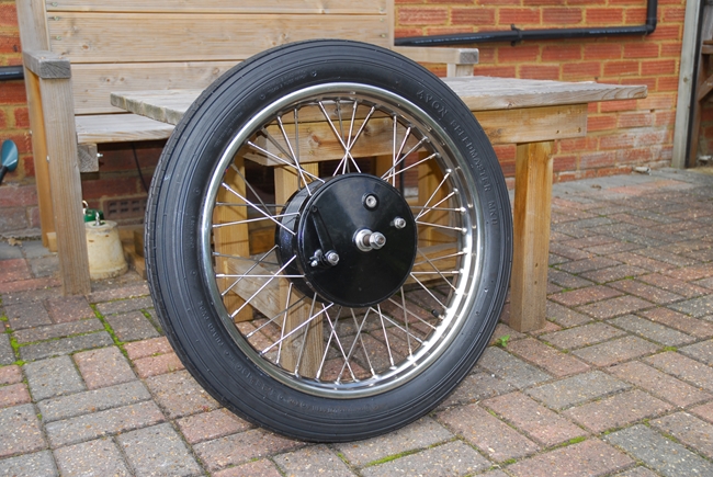 I've chosen to go with the classic Avon "Speedmaster" front tyre and I'll put an Avon "Safety Mileage" on the back to match it. With an old bike like this that probably won't do more than the legal speed limit, there's not a lot of point in buying more expensive, higher rated tyres and the choice in the sizes I need are very limited anyway.
This morning I re-assembled the wheel bearings. They're the 'old fashioned' taper roller type and need some careful setting up. It all went together without any drama, fortunately. I've fitted new grease seals and the old nuts have been replaced. The front brake plate went together without any problems, too. I filled up the hub with new grease and that's it for the front wheel. All done... I think it looks good in black, particularly as the rear hub was black as standard. The alloy hub and brake plate were badly corroded on the surface. A gentle vapour blasting and powder coating were the best option. The purists and 'rivet counters' won't like it but tough!!
Last Wednesday, after our pub lunch, Les and I went over to see Ernie. He was just on his way out but he said that the painting will be "done by next Wednesday." so we'll go over again in a couple of days time. Hopefully, he'll be true to his word. [Well, not quite. He phoned me on Tuesday evening to say that unfortunately, the paintwork wouldn't be ready until Saturday morning. That isn't going to be a problem in the greater scheme of things.]
Saturday, 5th August, 2017. I collected the bits from Ernie this morning and I have to say... it was worth the wait. The swinging arm is better that I ever expected. If you compare the photo here with the one back up the page aways, you'll see what I mean. 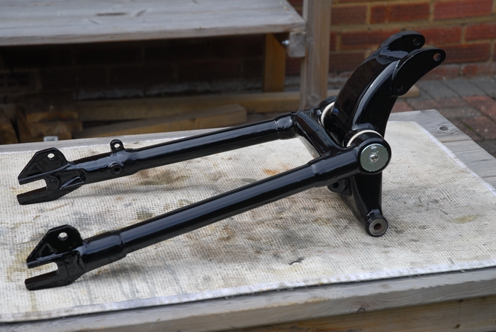 This afternoon I assembled the rear fork to the cast aluminium member that houses the bearing pivot pin. The original pivot pin was badly rusted and not serviceable so a new one was sourced from AMOC Spare, along with new end caps, gaskets and new felt washers. The bronze bushes in the rear fork were perfectly ok and were not replaced. However, as they are bronze, the bearing reservoir will be filled with GL-4 specification gear oil in due course as that is safe to use with 'yellow metals'.
The other task I completed today was to take the outer cover off the gearbox again. Having rebuilt it a few weeks ago and filled it with oil, I have discovered that the front cover joint is leaking very slightly. Probably because the joint faces showed signs of having been prised apart with a screwdriver or something similar by a less than sympathetic previous keeper. Instead of using a thin paper gasket and blue 'Hylomar', this time I assembled the cover 'metal to metal' with ThreeBond 1184 sealant. I'm confident that it won't leak now.
Monday, 7th August, 2017. Things have been a bit slow over the summer and I'm not as far ahead as I thought I might be at this point. So... it's time to get things rolling again. Today, I rebuilt the rear suspension units. I'd bought a boxful of bits from another AMOC member a few weeks ago but while there were enough parts to assemble a couple of 'Jampots', it was obvious that 60 years of wear and tear had taken their toll and some of the parts would need to be replaced. Fortunately, all the parts I needed were available and over the last few weeks, I'd collected together the bits I needed. The new top spring covers were already painted black but it looked like it was a quick spray over with a rattle-can and not a 'proper job'. They've been over to Ernie and given the treatment... etch primer, black gloss, flatted off and clear lacquer followed by a polishing. Much better!! The bottom spring covers have been replaced with polished stainless steel items as the chrome on the ones I had were well rusted. Internally, the plastic bearing bushes have been replaced with a machined bronze bushes and of course, the oil seals have also been replaced along with the top mounting 'O' rings and the leather washers each end of the springs. So all I had to do was put them together... easy, peasy... NOT! The springs, inside their upper and lower covers have to be compressed and a wire 'circlip' fitted to hold it all together. They say that 'necessity is the mother of invention' so I 'invented' and fabricated a fixture that would allow me to compress the springs and more importantly, hold them securely while I fitted the circlip. The following photos show it all a lot better than I can describe it.
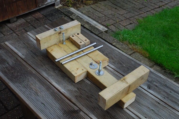
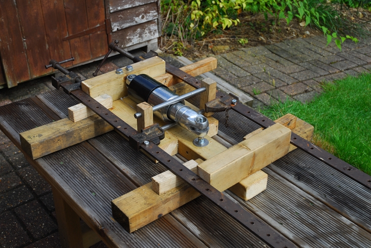
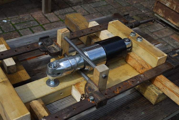
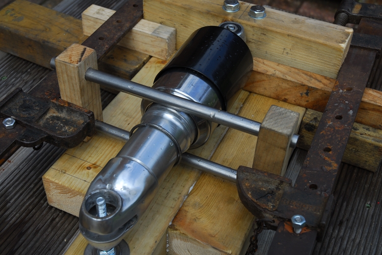
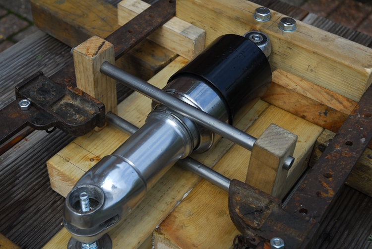
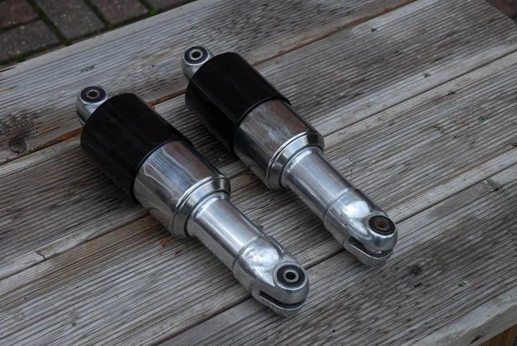
Sometimes, I'm staggered by my own ingenuity. The cobbled together collection of spare timber and metal worked flawlessly and I now have a pair of fully reconditioned 'Jampot' suspension units. Hopefully, later this week I can start putting the frame together. Once I have a 'rolling chassis' it really will start to look like a motorcycle.
Friday, 11th August, 2017. Rain has stopped play for a couple of days but I've not been idle (or any more idle than usual, anyway). The 'tin-ware' that I got with the bike, mudguards etc., had suffered the worst over the decades of storage. There wasn't much that was realistically salvageable. If it had been a 1920's Brough Superior, then it might have been worth the time and effort to restore but a '54 Matchless... hmmm, I don't think so. So what to do? Finding good, second hand original parts is difficult. They are the best part of 60 years old and most are not much better that what I've got. Those parts that have survived better are ridiculously expensive. I needed both the front and rear mudguards. I had thought about buying a pair of "generic" alloy 'guards but to be honest, that didn't really sit well with me so I cast further afield... to India in fact. I've managed to find a pair of new, reproduction mudguards from a guy in New Delhi. A little haggling and hopefully, they are on their way to me. Time will tell if it was a wise investment.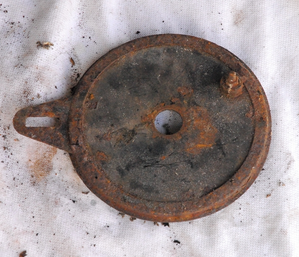 So, what else have I done this week? With the front wheel finished and the rear hub away having a new rim laced on, I thought it was about time I looked at the rear brake. The drum/sprocket was rusty but it looks serviceable. A good going over with a wire brush and a coat of black paint and it will be OK. The brake drum has surface rust on it but doesn't appear to be scored and the teeth on the sprocket aren't 'hooked' so I'll re-use it. The brake plate and brake shoes are another matter. Having stripped it apart, the shoes are good. They'll need new linings but that isn't a problem. There are any number of places I can get the shoes relined. The plate itself has corroded too badly and rusted through, close to the anchor lug. It's not good enough to use as it is and not really worth the time and effort to refurbish. Fortunately, eBay came to the rescue and I've found a much better example for just a few of our fine British quids. It is on it's way to me as I type this. It'll need cleaning up and a coat of paint but it's structurally sound and more importantly, it will be safe to use.
Setting up the ignition timing on the engine was the next task. I had a bit of a dilemma with that. The '54 G3/LS was originally fitted with a Lucas N1 magneto, that was chain driven from the exhaust camshaft and mounted in front of the engine. I have all the bits to do exactly that but the magneto that I have is U/S, dead, modus non-operandi. That is unfortunate. Conservatively, it will cost the wrong side of about £300 to recondition the magneto and currently, the specialist companies that carry out the work are quoting up to 6 months lead time.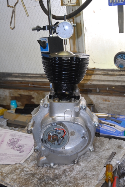 I have a 'Plan B'. The purists and rivet counters aren't going to like it but to be honest, I don't give a toss. Amongst the bits I bought from Malcolm was the bottom end of a 1960 500cc AJS Model 18 engine. By the time that engine was produced, AMC had brought the bikes up-to-date with alternator charging and more importantly, contact breaker and coil ignition, driven from the inlet camshaft. On the face of it, as the crankcases were (more of less) identical, all it needed was the high lift camshafts, inner and outer timing covers, auto advance unit and contact breaker plate from the later 500cc M18 engine grafting onto the earlier 350cc G3 engine. What could be simpler and as I had the parts to hand, the only cost would be a new set points and a new condenser; a few pence by comparison!
The later cams slotted in nicely and I set up the valve timing. The problems began when I fitted the inner timing case cover. There was a tiny discrepancy between the dowels fitted in the earlier crankcase and their respective holes in the later timing cover. This meant that the camshaft bearings were 'binding'. It took some careful 'fettling' and a little T.L.C. to get everything right. The inner cover was on and the cams were turning freely. So far, so good. The next bit was relatively easy and something I've done numerous times. Hold the auto advance unit in it's fully advanced position, set the new contact breaker points gap to 0.015", turn the crankshaft to the correct 'advance', in this case with the piston 1/2" B.T.D.C. and adjusting the points plate until the the points were just opening. It's not rocket science. I was happy with the way things turned out and I'm sure it will work fine. Just need to find somewhere to mount an ignition coil and, of course, an ignition switch. The outer timing cover is a bit special but you'll have to wait a while to see that. The best part is that nothing on the G3 engine has been modified. If, at some point in the future, I or the next keeper want to put the magneto back, then it's just a case of putting the original parts back on. I have them all and will keep them for just such an occasion.
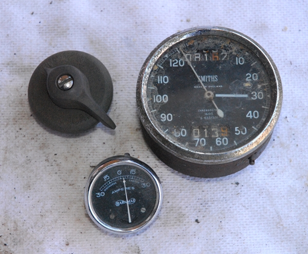 Tuesday, 15th August, 2017. It's time for another update. A lot of 'little stuff' has been going on in the background that I haven't, as yet, recorded here. Amongst the bits and pieces was a box containing a light switch, an ammeter and a Smiths 'Chronometric' speedometer. There was a problem, however... isn't there always? The switch was broken... but not un-repairable. I'll save that for later. The ammeter was not the correct one for the bike and the needle wasn't sitting at 'zero' anyway. That will be replaced at some point, which leaves the speedometer. This didn't look too promising either. It wasn't the correct model for the bike. This one goes up to 120 m.p.h and only way the G3 is going to reach that sort of speed is if I push it over a cliff. The needle is also stuck at maximum reading and the cable input stubbornly refuses to turn. As well as being incorrect (the Matchless should have an 80 m.p.h. speedometer), it's broken. There are a number of options. I can try to find s second hand one but genuine Smiths instruments are going for anything up to and exceeding £500 and there's no guarantee they'll work. I can fit a new Smiths electronic speedometer as I have on the Bonneville but they are £250 and I would have to convert the bike to 12v electrics. OK... maybe. I could fit a tacky Chinese reproduction job for £50... No, I don't think so. Or I could get this one repaired. I parcelled it up and sent it off to Chronometric Instrument Services in Nottingham. They did a good job on the AJS speedo so hopefully they would be able to do something with is one. I heard back from them a couple of weeks later. I was right... it was broken. The guy I was speaking to was optimistic, though... apparently, they'd "never lost a patient yet". They are going to do a "concours restoration" on it (their words), fit it with the correct 80 m.p.h. dial and re-calibrate it for the Matchless. What more could I ask?
The rear wheel is ready for me to collect from CWC. As well as the new stainless rim, they've also fitted a new Avon "Safety Mileage" rear tyre while they were at it. I'll go up one day next week to collect it. I'll also take up a load of smaller parts up to be powder coated. I'll probably drop in to the George & Dragon in Stoke Golding, the 'Brewery Tap' for the Church End Brewery, and have a pint of Goat's Milk, the "Champion Beer of Britain, 2017".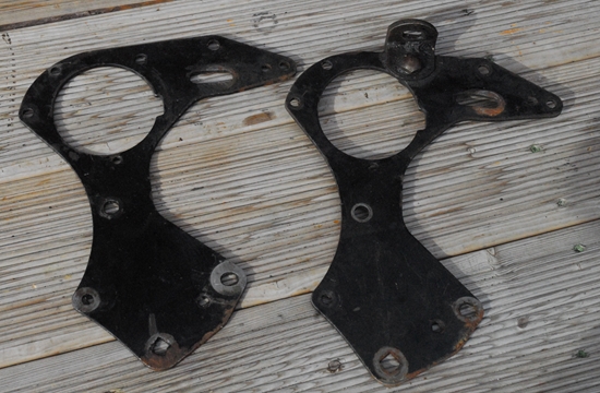 The second hand rear brake plate that I bought off eBay has turned up and is in much better condition than the one I had. That's been de-greased and will be among the parts that I'll take up for powder coating. I've already mentioned mudguards up the page a ways so that just leaves engine plates. There were a pair in the stuff I bought from Malcolm but they were very badly pitted and rust had eaten the steel away around some of the stud holes. They would be usable at a push, if I couldn't locate a better pair. A pair did come up on eBay some weeks ago and they looked better so I bid and won. Well... they weren't nearly so badly rusted but what the photo hadn't shown was the significant amount of wear around the gearbox stud holes. It was obvious that the bike they had been fitted to had been running with a loose gearbox and the mounting studs had worn and enlarged the holes in the engine plates. Hmmm, caveat emptor as they say. At least they did arrive with the horn mounting bracket bolted in situ. That was something that I needed so it wasn't all bad. It was while I was pondering my plight that I spotted an advert for some engine plates that had been laser cut from stainless steel. They weren't the plates that I needed but I contacted the people selling them anyway. They were a sheet metal company who were producing a lot of classic motorcycle brackets and plates from stainless steel; but unfortunately, not the ones I wanted. They were, however, always looking to expand their range of products and if I had a pattern they could copy, they would add my plates to their range and cut me a set, gratis, for my help. I sent them the four plates that I had. They should be able to determine all the dimensions they needed from them. My contact there, John T., did say it would take four to six weeks and as yet, apart from acknowledging that the plates had arrived, I've not heard from him but I live in hope.
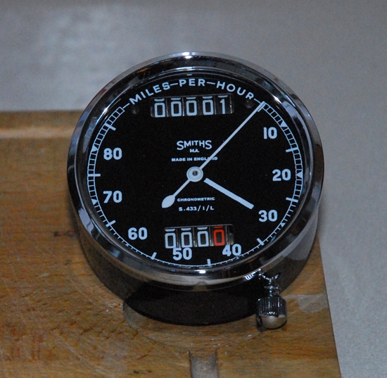 Thursday, 17th August, 2017. Today was a good day. I've had some deliveries, not the least of which was the newly restored speedometer from Chronometric Instrument Services. What a cracking job they've made of it. It's even got a chrome plated trip reset knob instead of the more usual black item. I love it. There was also the long frame stud and brake pedal bush that came from Andrew Engineering Ltd. That was the last of the frame studs I needed and I now have all the bits I need to put the frame together... I think!! The last item to arrive today was the second hand alloy gearshift lever for the Burman gearbox. I won that on an eBay auction. In fact, I was the only bidder so it came cheaply. Which is good as I've now exceeded my planned budget for this restoration... and I've hardly started!! Who was it who said that buying a 'basket case' and restoring it was the cheapest way to get an old classic? Yeah, that's right.... Nobody!!
With the rear wheel being collected next Wednesday, I started looking at what I would need to get that ready for fitting into the frame. I have all the bearings, spacers and grease seals for the hub so it was really the spindle and bits that go with that I needed to look at. I have the spindle and it's in perfect condition. I have the two 'snail cams' for adjusting the rear chain tension. They were pretty rusty but at forty quid for a new pair, I cleaned them up and gave them a coat paint. They will do nicely, thank you. I have the two spacers I need but what I don't have are the two spindle nuts, the two shouldered collars or the two woodruff keys for the snail cams. Fortunately, they are all available and not too costly. The speedometer drive gearbox was very dirty but one of the beauties of the old original Smiths gearboxes is that you can take them apart and clean out all the old grease and dirt. 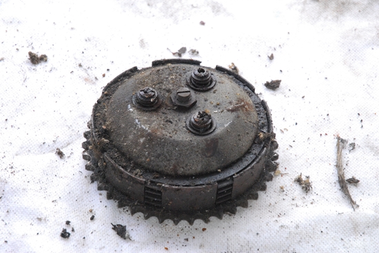 The gears are all metal too, unlike their modern counterparts which use moulded plastic. The last thing today was the rear brake drum / sprocket. That cleaned up nicely. The drum is pretty much perfect; smooth and without any scoring. After a serious wire brushing I gave it a couple of coats of etch primer, black gloss and clear lacquer. Looks almost brand new.
Tuesday, 22nd August, 2017. Another journey over to AMC Classic Spares yesterday. I now have all the missing parts for the rear wheel spindle so I should be able to assemble the rear wheel when I get it back from CWC tomorrow. Today, I thought I'd have a look at the clutch. If you've been paying attention, you'll be aware that this bike has a Burman gearbox. What it doesn't have is a Burman clutch to suit. 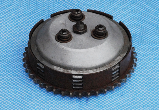 There are a couple of odd bits in one of the boxes but they are so worn as to be pretty much useless. What I do have amongst the bits, however, is what looks like a complete AMC clutch from a later bike. It was grubby... No, it was filthy... so I had it on the bench and took it all apart. Once I'd cleaned off all the accumulated muck, it turns out that I do indeed have a complete, 5 plate, heavy duty, clutch as fitted to the 1962 650cc CSR model twins and later heavyweight singles. What's more, it's in perfect condition (almost... more later). That's the good news. Yes, there is some bad news... It doesn't fit the Burman gearbox. Well, it does but it needs a spacer fitted on the gearbox mainshaft behind the clutch to bring the clutch sprocket into line with the engine sprocket. A little searching in "Christian's Archive", (the repository of all knowledge Matchless and AJS) was called for. I found that it's not unheard of for AMC clutches to be fitted to Burman boxes and I now have the dimensions of the spacer I need. It's not a 'standard' part, of course so I'll have to make one. I can see another trip to my sister's coming up to use my brother-in-law's lathe.
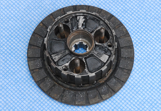
OK... back to the 'almost' perfect condition bit. This clutch differs from the Burman clutch in a number of ways but the most significant is that it incorporates a shock absorber in the clutch hub. This comprises 6 rubber wedges between the inner and outer parts of the hub. While I'd got the clutch on the bench, it made sense to see what sort of condition these rubbers were in. I have to say, they are not good. They've deteriorated into a soft, 'squidgy' sort of mess and will have to be replaced. I can get the old ones out and I'm confident that I can get 5 of the 6 new ones back in. What I am not so confident of is being able to compress the new rubbers enough to enable me to get the final one in. That may well tax my ingenuity somewhat. I'll worry about that when the time comes.
So ends part 1...
The saga continues... See "Part 2" by clicking HERE.
Link to G3 parts as bought from Malcolm.
Link to Index and Home Page.
Link to AJS M18S page.
Link to Triumph T120R Bonneville page.
Link to Triumph Tiger 90 page.
Link to Matchless G80CS page.
Link to Honda VFR750 page.
Link to Norton 650SS page.
Last updated 24/10/2021