Saturday, 8th October, 2022.
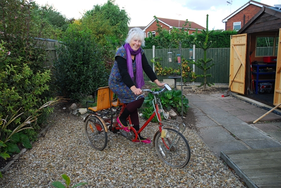
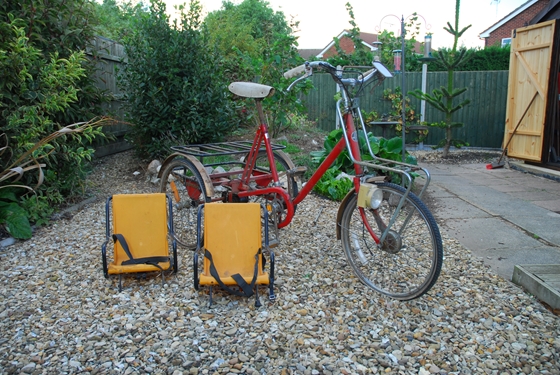
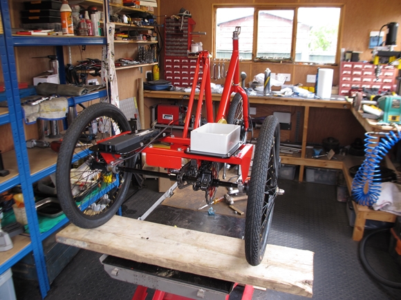
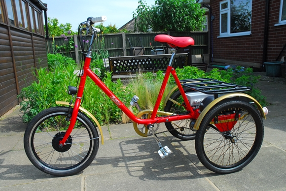
Christine came up last Thursday and brought with her an old tricycle that had been languishing in the back of the garage for decades. When her girls were younger, they were ferried around in the two seats attached to the back. As the girls are now grown up (and I use THAT phrase loosely!!) with children of their own, it's unlikely that they will ever need to be ferried around that way again. So, Christine thought that she might like to ride it again, and as a motorbike restorer of dubious reputation, I seem to have got the job of making it road-worthy again. Oh joy! The trike is Pashley Picador and was made in Stratford-Upon-Avon. Amazingly, the company is still in business and even more amazing is the fact that they are still producing Picador Tricycles. They are expensive, though at just under £1000 and are not fitted with an electric motor. Ho hum!!
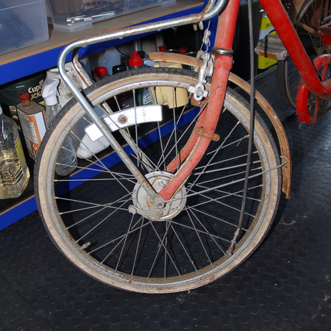 Having had a look round it, the trike doesn't seem to be in bad condition, considering. OK... there are a number of obvious things to look at. The tyres and tubes are totally shot but they can be replaced... if those sizes are still available. There is considerable rust on the painted parts and corrosion on those parts that have been chrome plated but that can all be sorted. Strangely, it has two front brakes and no rear brake. At the front, there is the normal cable operated calliper brake working on the rim, operated by a lever on the right of the handlebar and there is also a cable operated drum brake in the front wheel, operated by a lever on the left of the handlebar. That may be problematic as it is my intention to replace the front wheel with a new one which has an electric motor built into it. It will need another braking system installed as the single calliper at the front won't be good enough. I may be able to fit a disc brake onto one (or both?) of the rear wheels or possibly onto the rear axle.
Sunday, 9th October, 2022.
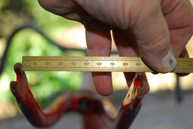
Hmmm.... I've had a better look at the wheels currently fitted, and the way that they've been fitted. The front wheel follows normal bicycle practice and fitted into the slot in the bottom of the forks. The rim is approximately 18.1/4" diameter but this is nominally a 20" wheel as the tyre is a white wall 20" x 1.3/8" item. There are a number of e-bike conversion kits available with a 20" wheel so that shouldn't be too much of a problem. What may well be a problem is the fact that the gap between the forks, where the wheel fits, is only 90mm. the majority of the conversion wheels require a 100mm gap. I may (or may not) be able to sort that with the application of some heat. A movement of 5mm on each leg should be do-able. Alternatively, I may be able to source a modern front fork that will fit the frame.
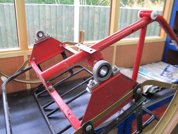
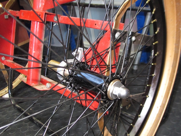
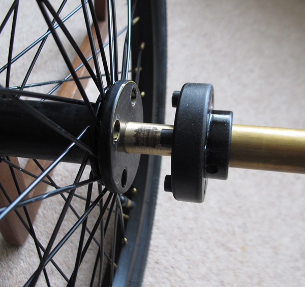
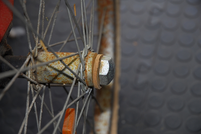 The rear wheels are a different matter entirely. It really is a bit of a bodge and something that I will be looking to correct before the trike goes back to Christine. The rear "axle" is a length of 3/4" diameter bar that is supported in two pillow bearing blocks. OK... that's acceptable. Only one of the rear wheels is driven by the pedals and permanently fixed to one end of the axle. The other wheel is free to rotate on the other end of the axle. With no differential, it would be tricky going round corners if both wheels were permanently attached to the axle. I've had a tentative pull at the fixed one but the hub is a bit "flimsy" and I'm just as likely to destroy it if I use any more force. The other wheel has been "worked on" by someone else in the past as there is no way any self respecting manufacturer would sell it in the state it's currently in. The nasty plastic bushes are badly worn and an oversize Tufnol washer has been fitted under the securing nut. The nut has to be left loose because if it's fully tightened, it locks the wheel completely. That is totally unacceptable, purely on safety grounds. On the plus side, the whole rear axle assembly is bolted to the rear of the trike's main frame. I think it will be simpler and better in the long run if I re-engineer the back axle completely, using proper bearings in the "free" wheel and make the "locked" wheel easily removable for things like puncture repairs and tyre replacement. This is turning out to be quite a project!!
Monday, 10th October, 2022.
Ok... Leaving the rear wheels etc. for the moment, as I've pretty much got that sorted out in my head, and returning to the front wheel and forks. This morning I had a chat with a very knowledgeable gentleman who runs a bike shop in Wisbekistan... sorry, Wisbech. I showed him some photos of the trike that I'd printed off and told him that I proposed to restore it. Anyway... after he'd got up and stopped laughing, he reckoned that it would be easier and less stressful to buy Christine a new electric tricycle.
I was having none of that and we started discussing wheel sizes. Now it turns out that none of the sizes quoted for bicycle wheels these days have much to do with the actual diameter of the wheel rim. The 20" refers to the overall diameter of the wheel, with the tyre fitted, and that depends on the diameter and width of the rim and the size of the tyre that will fit it. The wider the rim, the bigger the tyre that you need, so the rim has to be smaller to compensate and keep the overall diameter to 20". That's why the original wheel rim is 18.1/4" diameter and is fitted with a small section 20" x 1.3/8" road tyre. Just about all the 20" wheels that are fitted with a hub motor, use a rim that is 418mm (yes, the buggers have gone all Euro on me) with a much bigger 20" x 1.75" or 20" x 2.00" BMX style tyre. Keep up at the back there. Are you still with me?
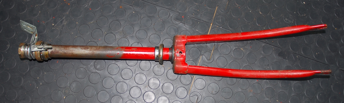
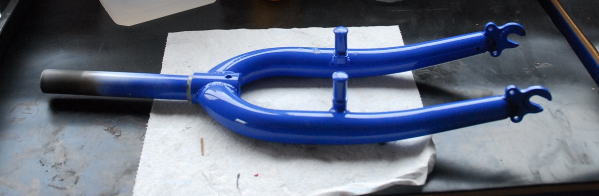
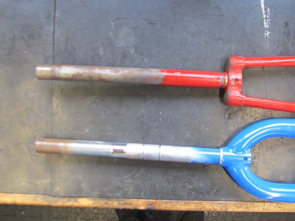
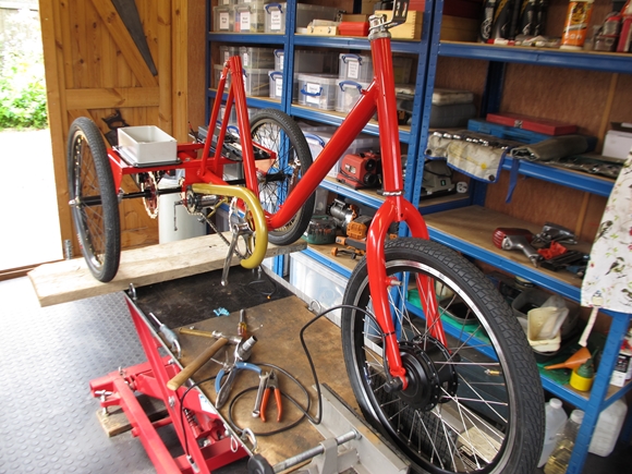
 Good... Cast a glance up at the photo of the front fork. You will no doubt notice two features. First the fork legs are closer together at the top than they are at the bottom, where the wheel fits. The legs are also too close together. As mentioned up the page a bit, the gap between these fork legs at the bottom is only 90mm. The gap needs to be 100mm for an electric motor. On all modern bikes, the fork legs are parallel to accommodate the bigger tyres, and wide enough for a motor. Secondly, the stem tube is exceptionally long; 12" or 300mm if we're going Euro. That's twice the length of most I could find on t'interweb. (For some strange and incomprehensible reason, these days, this tube is referred to as the "steerer"). OK... What does all this mean, I can hear you ask. Well... it means that I can't use the original fork with a motorised front wheel, and I can't use a new modern fork that will accept a motorised front wheel, 'cos the steering stem is too short to fit the trike frame. Come back later for the next thrilling instalment.
Having thought about it for a bit, the solution may not be that difficult. I've ordered two new sets of forks. Neither particularly expensive. One set has the correct length and width of fork legs for a motorised wheel, but the stem tube is too short. The other set is no good for the wheel but has the longest stem tube I could find. I also have in my workshop a length of cold drawn, seamless steel tube that is 1" diameter, the same as the stem tube. I will cut the long stem tube off one set, turn up a stepped spacing piece from the steel tube and 'sif-bronze' braze the parts together to give me the correct length stem tube on the correct fork legs. Oh yes... now we're cooking with gas!!
Wednesday, 12th October, 2022.
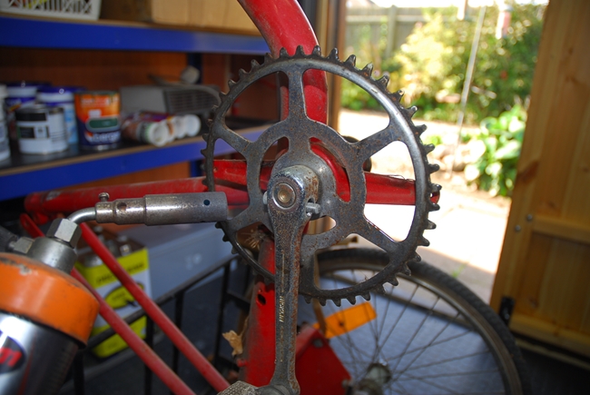 The dismantling continues... To start, the chain guard and chains (there are two) were removed; easy peasy. Next, the chain wheel and pedal cranks. They are the old style that uses a tapered cotter pin to secure the pedal cranks to the axle in the bottom bracket. I just knew that these would not give up without a fight... and I was right. It took a serious amount of heat and a sharp clout with a sizeable hammer before the pins dropped out. That was the easy bit. The locking ring unscrewed but I couldn't shift the bearing cup. Not because it was tight or rusted in, but because I didn't have a suitable tool to unscrew it. It required a peg spanner with 1/8" pins. While I have peg spanners, they all have pins that are 4mm or larger. A search on t'interweb only threw up one such tool with 1/8" pins, but that was in America (bless 'em for not going metric) but when the cost of delivery was added, it was prohibitively expensive. So I've ordered the next best thing, a peg spanner with 3mm pins. Until it arrives, sometime in the next few days, hopefully, this part of the dismantling is on hold. There is plenty more to do... As the chains are already off, I can have a look at the 3 speed Sturmey-Archer gear hub. It's an AW model, and they've been around since Christ rode a bike, but I've never had to take one apart before. This could get interesting.
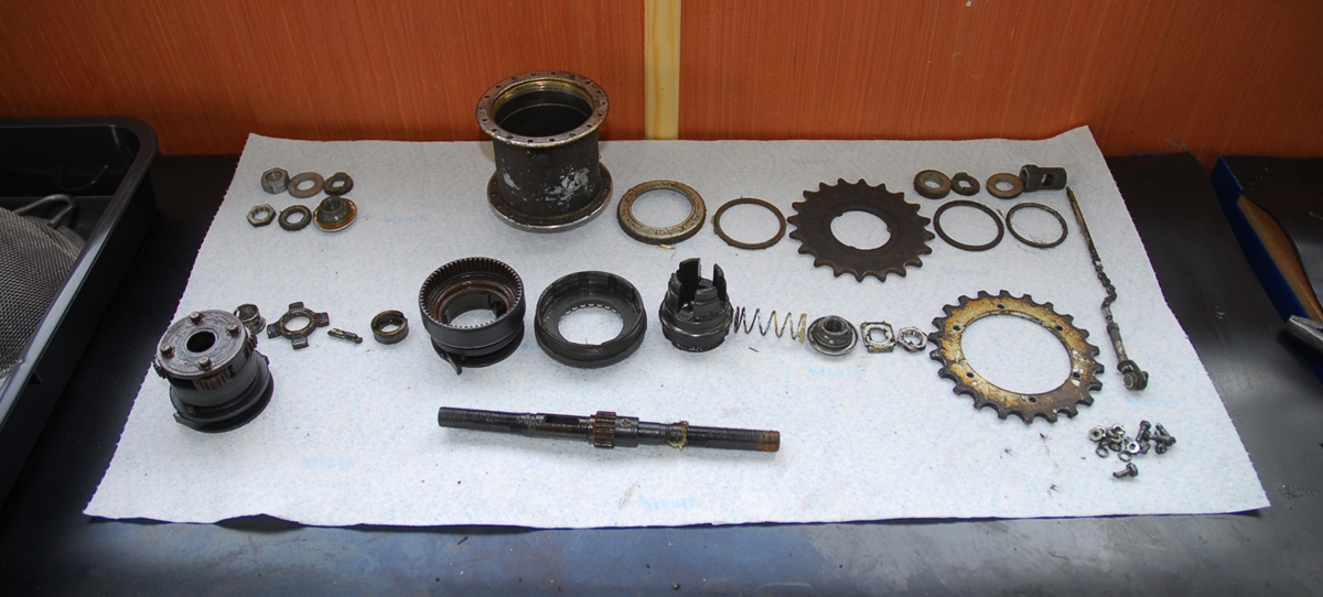
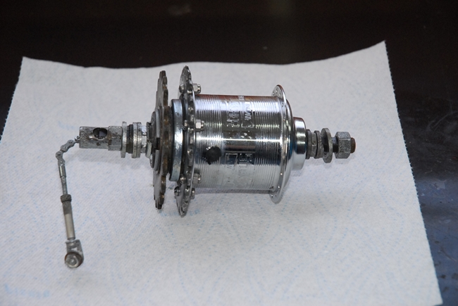
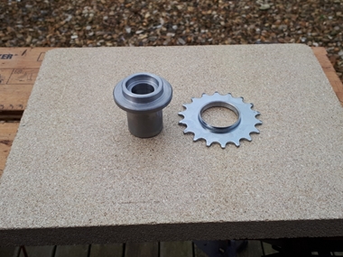
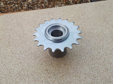
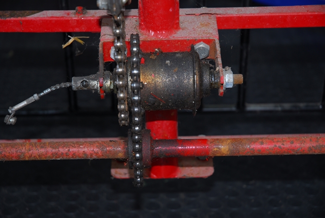 Whatever you need to do these days, somebody has already done it before you and made a video to post on YouTube. This was no different and I watched as a very nice gentleman took one apart, cleaned it, and put it back together again. It's not difficult if you follow the sequence and are careful not to lose the tiny ratchet pawl springs. More about that in a minute!! Normally, these units would be the hub of a rear wheel and a rim would be spoked directly to the hub. Pashley, however have adapted it as a counter shaft and attached a sprocket to the flange where the spokes would normally be. Quite clever, really. All I had to do was loosen the nuts on each end and it dropped out of it's mounting bracket on the bike. Taking it apart was really quite easy and straightforward. I followed the sequence shown in the YouTube video and laid all the parts out on a clean sheet of paper in the order that I took them off. It's a relatively simple "Sun & Planet" type of mechanism, similar in some ways to what you would find in a car automatic gearbox. It's robustly made and shows no sign of any significant wear; which is rather surprising, give the almost total absence of any form of lubrication. It had been assemble with a little grease, but that had long since dried out and was as much use as the proverbial chocolate teapot.
 I cleaned the various component parts and started to reassemble the gearbox. I coated all the parts with Castrol D, a straight SAE 140 gear oil as I put them together. All went well until I started to fit the ratchet pawls. The springs are tiny, bent from very fine wire and one of them was determined to escape. Three times it pinged out and twice I spotted where it landed. The third time, I didn't. I know it landed on the floor but I couldn't see it. Fortunately, it was magnetic and I managed to find it by passing a large magnet over the floor. Phew... That was the only problem, and the rest of the parts went back together perfectly. The three sets of cone and ball bearings were in perfect condition and reassembled with a Teflon based grease, designed for bicycle bearings. The only things I replaced were the six little screws and nuts that secure the output sprocket to the hub flange. They are now stainless 4 B.A. screws with locking nuts instead of the tiny ones that Pashley used. The unit felt a lot smoother and I'm sure it will perform exactly as it should when back on the trike.
Friday, 14th October, 2022.
Right... the first set of replacement front forks have arrived. This is the set that I intend to use in the trike's frame to enable me to fit an electric motor front wheel. At first glance, they look the business. They are the correct width where the wheel mounts and wide enough at the top for a modern front tyre. The much better news is that the head bearings that were on the trike originally, fit the forks perfectly. I was a bit worried that over the intervening years, the diameter and thread form would have changed, but it seems not... excellent! It is obvious, however that the colour is totally wrong and the steering stem is too short. Worry not, dear reader, it will be stripped and powder coated the correct colour when I get the main frame done. As far as the stem length goes, I mentioned up the page a ways that I could extend that so I've ordered the second set of forks that are totally the wrong wheel size but have a much longer stem. They will be cut and brazed together along with a short length of steel tube to give me the correct length stem.
Friday, 21st October, 2022.
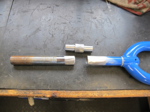
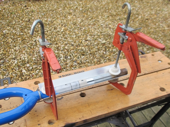
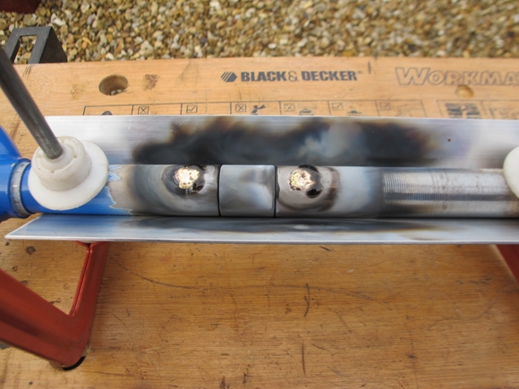
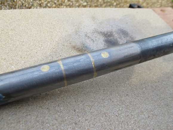
Things have been progressing slowly over the last week or so. I've been collecting parts that will be needed and now have enough stuff to get moving again. The first job was to extend the steering stem on the new front forks. I've done exactly as I said I would, the longer stem was cut from the scrap forks I bought for the purpose. The thread has been cut from the top of the stem on the forks I intend to use and a short length of 1" o/d cold drawn steel tube has been machined to fit and extend the stem to the correct length of 12". All I had to do today was stick the lot together. Oxy-acetylene and Sifbronze brazing rods being my adhesive of choice. I drilled 6mm holes in the two stem parts (but not in the joining piece) so that the parts could be plug-brazed together before I brazed the two joints. The parts, I clamped into a short length of aluminium angle to hold everything straight and true whilst I carried out the brazing. I was more than happy with the final result.
Friday, 28th October, 2022.
Some progress has been made, or maybe not... The new bearing blocks for the back axle have been temporarily fitted in place. They will come off again when the frame eventually goes off for powder coating. I've made up some supporting plates from 5mm thick stainless steel. These will give some added strength to the bearing mounting on the frame which is thin mild steel. I'll be using all new nuts and bolts, of course, and these I'll upgrade to stainless steel flange screws with stainless "Nyloc" nuts and washers.
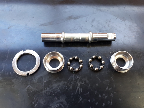
I've also turned up blanking plugs to fit in all the places that I don't want the powder coating to reach... The inside of the steering head tube and the bottom bracket which is threaded on the inside for the pedal crank bearings. Talking of the bottom bracket... The peg spanner with the 3mm diameter pegs arrived a few days ago and I was finally able to disassemble the pedal crank bearing assembly; after I'd realised that the right hand bearing cap had a left hand thread!! Ho hum... I had considered fitting a modern, sealed ballrace cartridge bearing, but that would mean using a modern BMX style cotterless chain set and that wouldn't suit the style of the trike at all. Fortunately, the bearings and pedal axle were in excellent condition under all the dirt and dried on muck. They've cleaned up well and will, in due course be re-assembled into the bottom bracket of the frame.
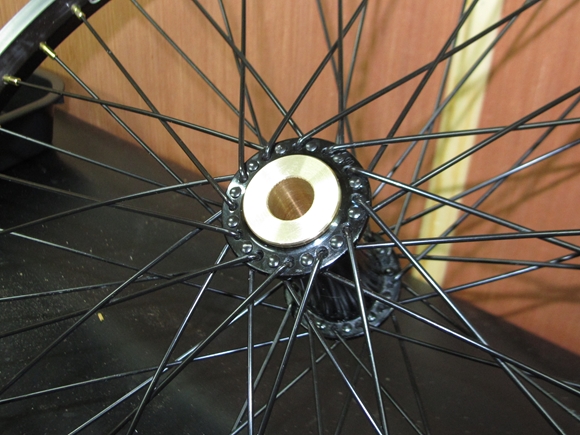
Right... It's official... I am an idiot! Have I mentioned that I've acquired a pair of new wheels for the back end of the bike? No, I thought not, well I have. They are front wheels, intended to be used on a bicycle.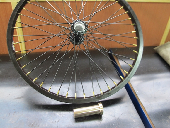 They will, however be perfect for the back end of a trike. I just have to re-engineer the hubs. I removed all the bearing components as they are unsuitable for what I intend and will no longer be required, then the hubs were reamed to make the bores cylindrical and true. They will be treated differently as one has to be fixed to the new back axle and the other has to be free to rotate. The actual rotation of the 'free' wheel on the axle, when in use, is not very much. Peddling straight, there is no relative movement at all. It's only when going round a corner that there will be a little difference, so in truth, the bearing doesn't need to be very sophisticated. It does, however, need to be a bit better than the bits of plastic that were fitted originally. I had look at what material I had laying around and found a shortish length of thick wall brass tube. I put a rule across it and it was 1.1/4" outside diameter. The hole through the centre looked to be just over 1/2" so that could be bored out to 15mm to fit the new back axle. Perfect, I thought. I then spent the next hour turning up a new bush to be pressed into the wheel hub. It was only when I came to bore out the centre that I found that not only was it just over 1/2", it was just over 15mm as well and no good for what I intended. Bummer. Should have measured it more accurately before I started... Ho hum!
Sunday, 30th October, 2022.
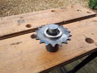
I put the rear wheels aside for the moment and started looking at the back axle. I already had the length of 3/4" bright mild steel for the axle itself but I needed to machine the carrier for the new sprocket. I'd already acquired a piece of 50mm diameter EN3 mild steel, 50mm long for just that purpose. A couple of hours on the lathe and I had the carrier I needed. The sprocket fitted nicely and the hole through the centre was bored to be a sliding fit on the new 3/4" diameter axle. All that was needed was to stick the two together. Time to fire up the oxy-acetylene again.
Thursday, 3rd November, 2022.
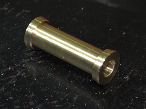
It was back to the rear wheel today... This time I turned up the brass bearing bush from solid CZ121 brass. It didn't take too long and I was happy with the result. It's not fitted permanently yet as I'll need the bush to use as a gauge when I come to turn the ends of the rear axle. The bush has been reamed to exactly 15mm diameter, the same as the axle bearings.
Friday, 4th November, 2022.
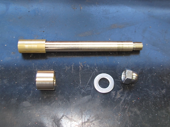
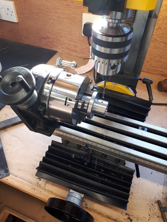
As you will no doubt be aware, dear reader, there are no plans or drawings for the restoration/modifications that I'm carrying out to this unfortunate tricycle. Yes, you are right... I'm making it up as I go along. However, there will come a time, in the not too distant future, when I will have to turn a length of 3/4" diameter steel bar into a functioning rear axle. I only have one bar of steel, so I'm only going to get one chance. I need to know exactly what I'm going to do. To that end, I've invested a little time and money in machining up a brass "dummy" axle end for the freewheeling rear wheel. That worked out very well and I now know exactly what I'm going to do to the bar of steel... on that end at least. I will be doing the same to the fixed wheel end in the coming days/weeks. Once that's done, I'll finish machine the rear axle, then I'll be one step closer to completing the restoration.
Tuesday, 20th December, 2022.
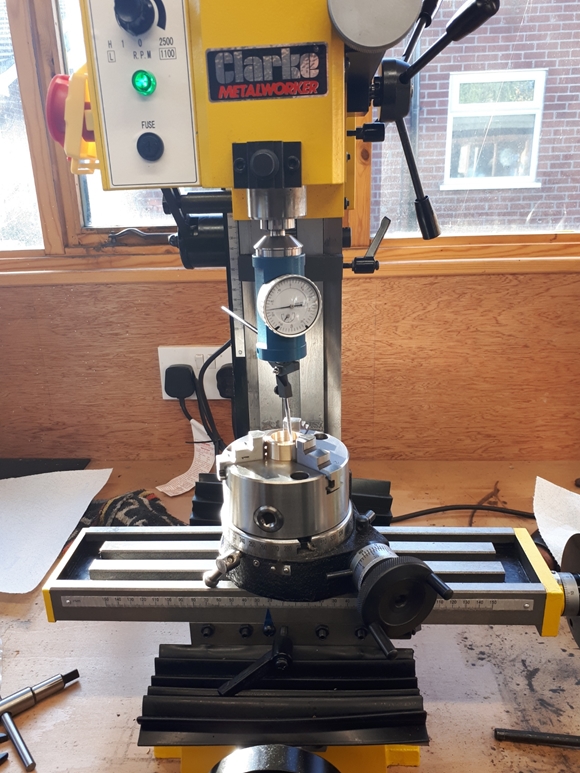
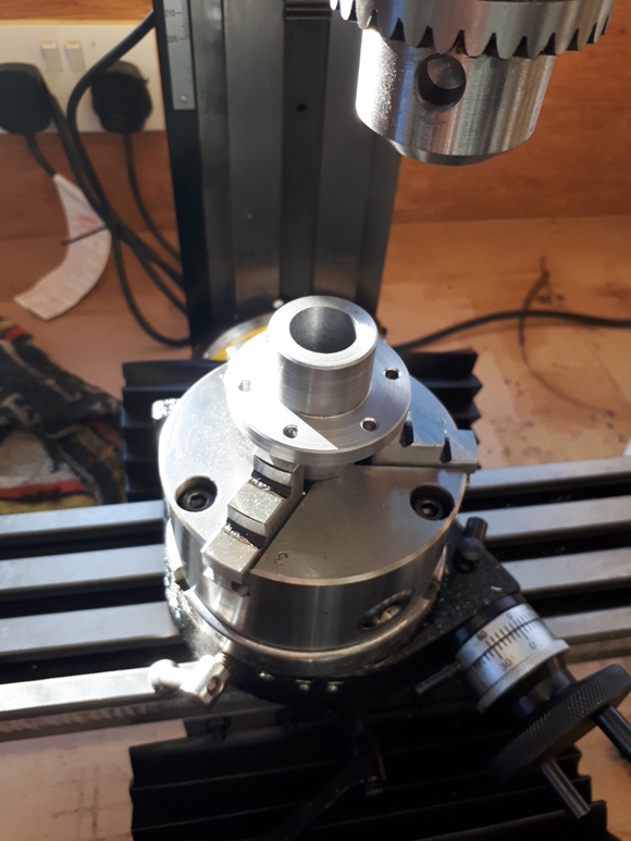
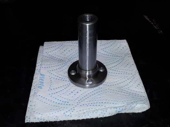
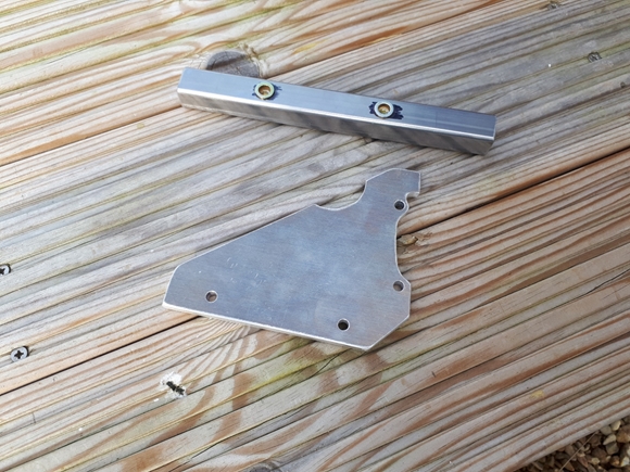
I apologise, dear reader, for my tardiness in bringing you up to date. Life and other projects have meant that the renovation of Christine's trike has had to be temporarily put on the 'back burner'. Some progress has, however, been made. Namely, the rear brake disc carrier has been machined from a lump of En3 mild steel and is ready to be fitted to the rear axle on final assembly. The following photos show it better than me trying to explain.
Sunday, 8th January, 2023.
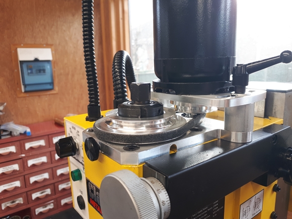
Christmas has come and gone; the work on the Triumph T90 has been completed so it was time to pick up where I left off on Christine's trike. I had a problem with the small milling machine, which was resolved by importing a belt drive upgrade kit from Pasadena, California. The first item on the agenda was the drive wheel axle coupling. The first part has been completed and will, in due course, be fitted into the rear wheel. This will allow me to take measurements for the mating part which will be secured to the new axle.
Wednesday, 25th January, 2023.
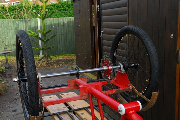
 A little more progress has been made. New tyres and tubes have been fitted to the wheels. The drive coupling for the rear wheel has been completed to my satisfaction and seems to work. Now, it's time to actually get to grips with the rear axle. I'd made "dummy" axles for both wheels and that has allowed me to make a rough drawing, with dimensions for the rear axle proper. I have the material, I have the drawing; what I don't have are the facilities to make it myself. The 3/4" diameter steel bar is too big to fit into the head-stock of my Myford lathe. I do have options, however.
"Howie", one of the guys I see in my local pub, has offered me the use of a larger lathe in his workshop. That was very kind of him but unfortunately, not really very convenient. It's something I will bear in mind and fall back on if all else fails. Another option was to find a local engineering company that would do the work for me... for a price. Small engineering companies that would take on a small, one-off job are a bit thin on the ground these days. There was one company, locally, that looked promising. The advertised themselves as doing "Precision CNC, Lathe, Fabrication & Welding Work". Their website looked promising and had an on-line contact form, so I contacted them. I gave them a brief description of what I wanted and asked them to get back to me if they were willing to have a look at it. They emailed me back within a couple of hours. This morning, I pitched up at their suitably scruffy and well worn premises, about a quarter of a mile from where I live, at the arranged time and spoke to Mr Bhavin Jayswal. He took my drawing and the steel bar... not a problem. I left it with them and he will give me a shout when it's ready. A cash deal; beer money for him, a job done for me. I love rural!!
Thursday, 26th January, 2023.
I hate rural!! So much for "Plan B". Just had a 'phone call from a guy named Ben at the engineering company. He's the one machining the axle for me. He'd turned the diameters ok, but had totally buggered the 1/2" UNF threads on the ends. I don't know how worn the die was he used but it rendered the whole job scrap. They are going to replace the 3/4" steel bar and I have loaned them my brand new Presto HSS die which I know produces a good thread. Hopefully, they'll get it right the second time. Ho hum...
Friday, 27th January, 2023.
 I collected the machined axle this lunchtime. They've almost got it right. Not exactly to drawing but I can work with it. I probably won't be using them again. At least it all goes together as I intended it to. The rear brake calliper is the next item on the agenda. Having offered it up in position, it looks like it will be a relatively simple job. I've ordered a piece of 8mm thick alloy plate and a short length of 20mm square steel tube. I think that's all I'll need.
That will be most of the 'engineering' on the rear end completed, I hope. I still have to think about mounting the battery and motor controller but until I decide which of the systems I'm going to use, and there are many to choose from, I can't do much about that. It will soon be time to think about putting it all together and making sure it's all ok before taking it all apart again. Then I can take all the various parts for powder coating and painting.
Sunday, 5th February, 2023.
 The trike has been moved into the workshop as it will be easier to work on it there. The rear sprocket has been secured to the axle in the right place with Loctite 638 and a 4mm stainless steel roll pin. It's there for good, now. I hope nobody has to take it off again anytime soon!!The next job is to sort out the rear brake disc and calliper. Hopefully, I can get on with that in the not-too-distant future.
Friday, 10th February, 2023.
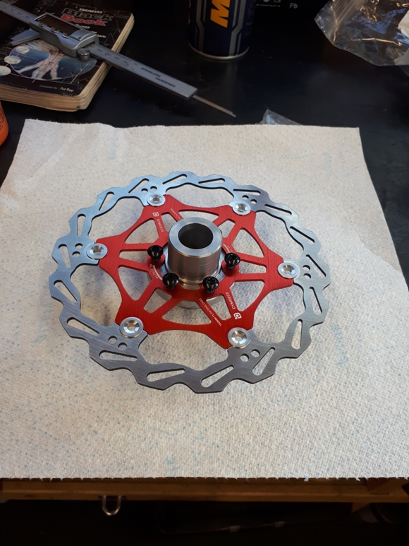
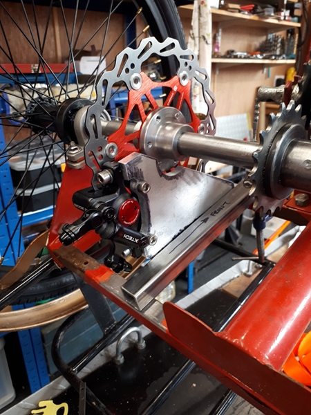
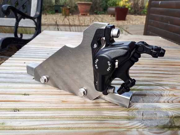
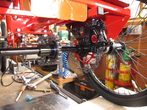
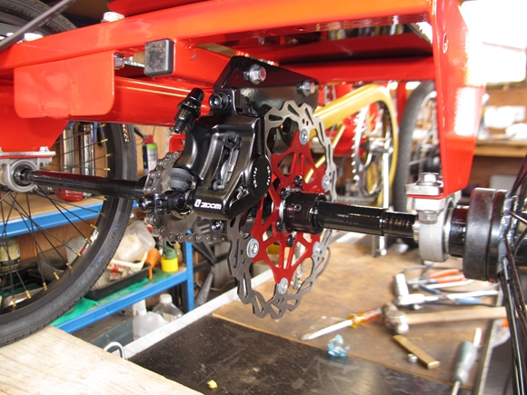
The engineering on the rear axle is just about complete. The brake disc carrier has been secured to the axle with Loctite 638 and two 4mm stainless roll pins. The calliper mounting has been completed to my satisfaction. The calliper itself is a hybrid 'state of the art' cable operated but hydraulically actuated unit.
The calliper mounting is massively 'over-engineered'. The mounting plate is 8mm thick, grade 5083 aluminium plate which is attached to a short length of 20mm square, 2mm wall thickness, steel tube with two stainless M6 flange screws. The tube has two M6 rivet nuts inserted and will be brazed to the axle mounting frame. The brake disc is a 160mm diameter stainless, fully floating unit. Hopefully, it will do the job. The steel tube will be powder coated red with the axle frame The mounting plate I'll probably do gloss black as a bit of a contrast. The carrier fame that's currently on the trike was gloss black once and I'll get that powder coated black again in due course.
It will soon be time to think about which motor / front wheel I'll be using. There are numerous options ranging from street legal, 250w motors right up to stupidly fast 1500w motors. I really don't think that Christine will be wanting to travel at 50mph so it will be a street legal job, but there are still a lot to choose from. I'll think on it some!!
Thursday, 23rd February, 2023.
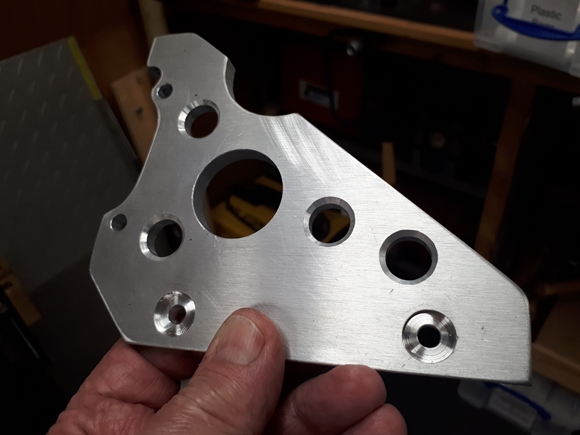
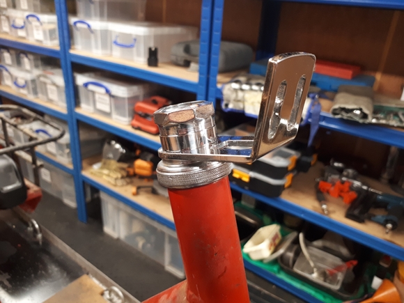
Things have been progressing slowly, I'm afraid, but some progress has been made. The calliper mounting tube has been brazed to the axle frame and I've drilled the aluminium calliper mounting plate. Not for lightness, particularly, but just for effect. It looks a little less like a great slab of metal, now. I've also turned up and polished a stainless steel spacer ring for the steering head. That's required to replace the original front brake cable mounting that will no longer be needed.
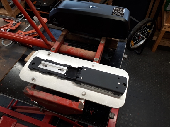
I've also taken the plunge and ordered a motorised front wheel and a 36v battery to suit. I hope that the one I've chosen will do the job. There were so many to choose from. I've also decided how the battery will be fitted and I've ordered a piece of aluminium plate that will be bolted to the top of the axle mounting frame. When the controller arrives, I'll be able to see just what size of box I'll need to hold everything. That will also be fixed to the top of the axle frame as well. That's the plan, anyway, but as you've already surmised, I'm making this up as I go along so anything can happen!!
Wednesday, 1st March, 2023.
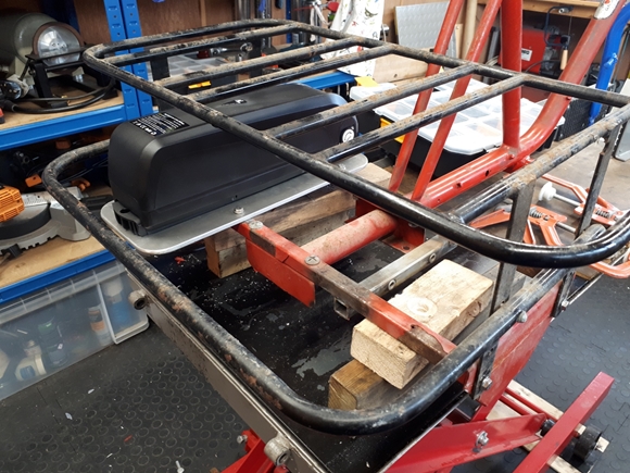
The battery and the new front wheel have arrived. This morning, I fitted a rim tape, tube and tyre to the wheel. I've also mounted the battery onto the aluminium plate. That plate has been fitted to the top of the axle frame, under the carrier frame. That will afford it some degree of protection. The battery can be removed from it's connection block for charging, but is locked onto it when in use. You can't remove the battery without the key, or a big hammer!!
Thursday, 2nd March, 2023.
This morning, I fitted all the electrikery to the bike. I needed to know if the cables were long enough to reach the back of the trike, where I had planned to fit a box for the motor controller module. I needn't have worried, they were plenty long enough. One thing I did find was that the "pedal assist sensor" was designed to fit on to a sealed cartridge type of bottom bracket bearing, not the cup and loose balls type that the trike had originally been fitted with. This time, I have to say, that luck was on my side. I had a brand new 68mm x 120mm sealed cartridge that I purchased some time ago for my own bike and never used. I was somewhat amazed that the screw threads were identical to the trike... they hadn't changed in 40 years!! The cartridge screwed straight in without any problems. It does mean, however, that I will have to source a new chain set to suit the new bearing. I hope the chain alignment will hold true. I need to mount a waterproof box next to the battery to hold all the connections and the controller. Once that is done, it will be time to take it all apart again and prepare it for painting.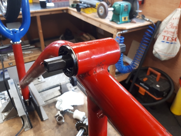
Tuesday, 7th March, 2023.
 A couple of things... The chain alignment wasn't good with the 120mm wide cartridge bearing, it was about 5mm adrift. I needed a shorter bearing. Fortunately, they come in a range of sizes and in the great scheme of things, aren't that expensive at around £10. A 113mm version was available and that would hopefully move the chain wheel closer to the frame and give a correct chain alignment. I'll find out when it arrives!
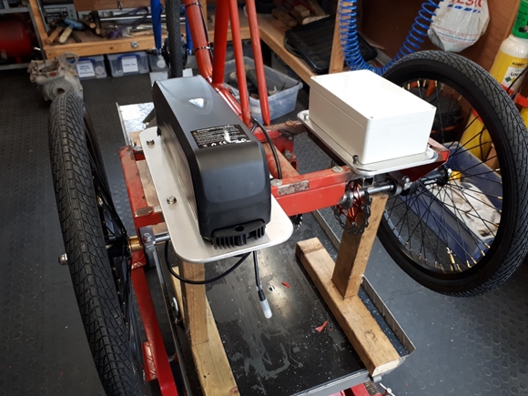
I've also acquired a waterproof enclosure for the motor controller and electrical connections. I've made up a mounting plate and that will be attached to the axle frame in a similar manner to the battery. I think that's just about all the 'engineering' work done. I still have to mount a pair of rear lights and fix the drive coupling to the axle but they will be completed once the frame has been painted. Hopefully, I'll have it completed for when Christine returns from her trip to Australia and New Zealand at the end of April.
Tomorrow, I'll be taking the carrier frame and the aluminium parts that I've made down to Richard at Breckland Finishing to be powder coated gloss black. Once I've sorted the chain alignment problem out, I'll be taking the whole thing to pieces again ready to have the frame, forks etc. painted red and the mudguards gold as Christine wants.
Thursday, 16th March, 2023.
First, the 113mm bottom bracket bearing will do just fine. The pedal chainwheel and the gearbox sprocket aren't exactly in line but they are close enough, particularly when you think about it in relation to bikes that have derailleur gears and the chain can be anything up to 50mm out of line on those and still work!! The PAS sensor fits where it should, although I did have to remove a segment of material from the chain guard support plate to clear the PAS cable. That just leaves the one thing that I'd forgotten about... fitting the front mudguard. It bolts through the forks at the top, that's just fine but it also needs a support stay at the bottom. I think I may have found one that will do the job... It's intended for a Raleigh Chopper but I think it will fit. I won't know until it arrives.
Saturday, 25th March, 2023.
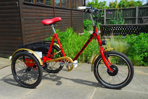
Yes, it did. It fits perfectly... hooray. That meant that the trike was now ready to be painted. I've taken it all apart again and it's now with CWC in Coleshill for the frame and forks to be powder coated "Traffic Red". The mudguards and chain cover are to be powder coated "Bonded Gold". Unfortunately, CWC are very busy at the moment and it's unlikely that I'll be getting the parts back it time to have it assembled and tested before Christine returns from her adventuring at the end of April. Oh, well... She'll have to wait.
Friday, 31st March, 2023.
Just a short note to say that the parts that I took down to Breckland Finishing to be powder coated gloss black were collected this morning. As usual, they've done an excellent job.
Thursday, 18th May, 2023.
The remaining powder coating has been collected from CWC. As expected, they've made a lovely job of it. Now, I've started to put things together, hopefully for the final time. So far it has all gone well. There may, however, be a small problem. Having got the pedal / chainwheel assembled into the bottom bracket, the left hand pedal is closer to the battery mounting plate than I would have liked. That's my fault as it was one thing I didn't check... I just assumed it would be ok and as we all know, "assumption is the mother of all fuck-ups". I will measure the clearance I have on my bike and compare the two. If the trike clearance is no less, it should be ok.
Monday, 22nd May, 2023.
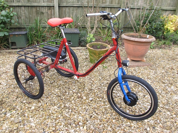
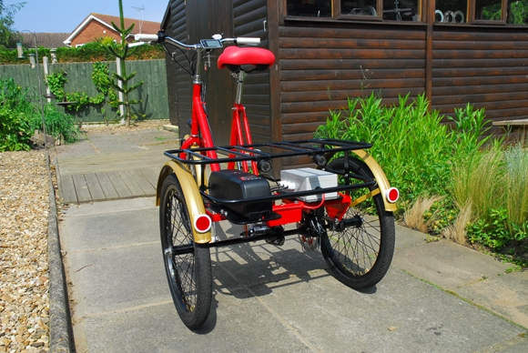
I decided to move the battery mounting plate back by 1.1/8". That's as far as it can go, and I'm confident that it will be ok. The trike is now fully assembled, and is, to all intents and purposes, finished. I took it out onto the road for a brief test ride... Ho hum, the "pedal assist" doesn't seem to be working. The motor started up using the thumb operated speed controller, but it didn't kick in as it should when peddling. In the end, that was a simple fix. The PAS sensor isn't bi-directional as I thought and I'd mounted it on the right (wrong) side of the pedal crank. The motor kicked in forward when you peddled backwards... not ideal!! It was a relatively simple job to take the sensor off and mount it on the left (correct) side of the crank. Job done.
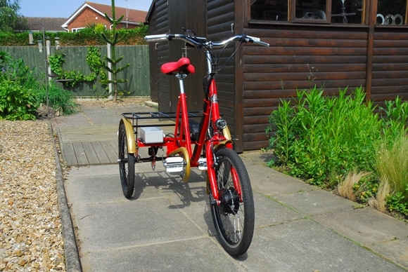
The control panel on the handle bars is a lot more sophisticated than the 15 year old one on my electric bike and needed "setting up". Apart from indicating the power to the motor, it displays speed and distance travelled. You can also set a maximum speed limit. For these function to work, you need to set the wheel diameter (20" in this case). You can also choose whether it displays in imperial (miles) or metric (kilometres). I've set the maximum speed to 15.5 m.p.h. which is the legal limit on the road in the UK. However, as Christine has intimated that she's going to ride it on the pavement, I may well set the maximum a lot lower, at least until she gets used to it. I've tested it out on my potholed and patched rural road and I found it quite a handful. In fact it was downright bloody dangerous. It will be better on a smooth, flat surface... probably!!
Tuesday, 23nd May, 2023.
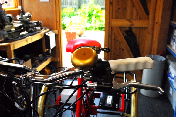
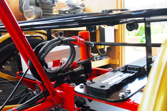
The last little bit of "tinkering" has been done... I've fitted a "Kryptonite" lock and cable. That fits nicely between the battery and the box of electrics. It clips into the holder and is easily removed when it's needed. The last item was a warning bell on the handlebars, coloured gold, naturally, to match the other gold parts. And that, my loyal reader, is that. Job done!!
Tuesday, 6th June, 2023.
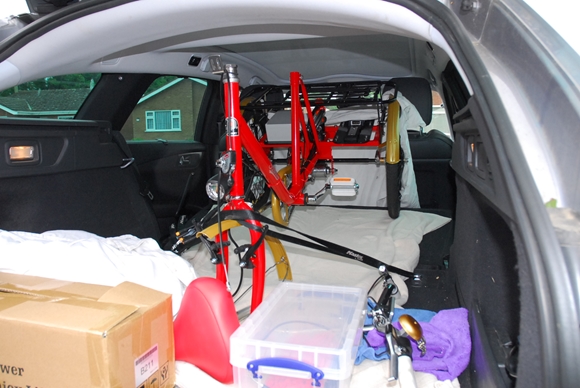
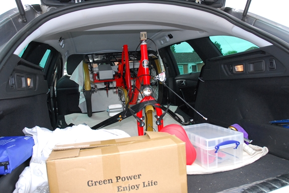
Just a postscript, really. The trike has been partially dismantled, and loaded into the back of my car. I had hoped to hire a small van locally, but the hirers told me I'm too old... Their age limit is 72. Anyway, tomorrow it will be taken down to Christine. It's been a while since I started this project and it's good to have finally completed it. How much did it all cost? Well, I did get some change out of £1500 and Christine insisted on paying for some of that.
Last updated 06/06/2023