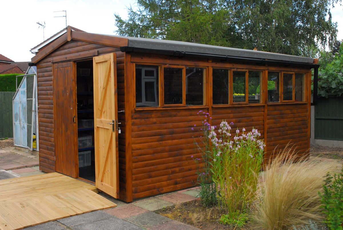
I now live in a detached bungalow on the edge of the quiet little market town of Long Sutton in rural Lincolnshire. Oh joy... There was room at the rear of the property to erect somewhere big enough to work on my 'bikes in some semblance of comfort. That 'erection' has now been completed and I have a timber workshop 10ft wide by 16ft long. Big enough to work on a bike with room to spare. The first 'customer'... Bess, of course.
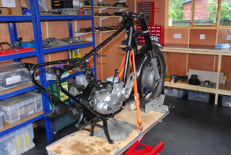
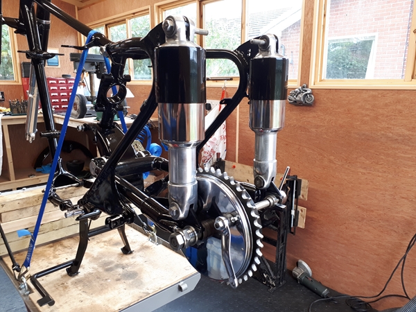
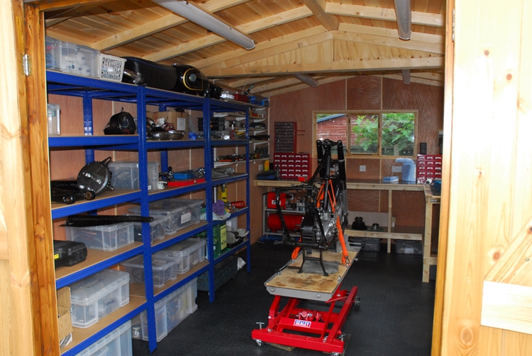 As you can see, Bess has been brought in from the cold and I've started work dismantling her. This time she will be completely taken apart. I'd like to find out if she really is a bit noisy, mechanically or whether it was my imagination. I also expected to find a few little surprises left for me by the PO (previous owner, remember?). I wasn't disappointed... or rather, I was... fairly quickly. Something I should have noticed before but failed to do so. I'll put that down to unfamiliarity with the machine at the time.
One of the first things to do when taking the bike apart was to remove the footrests. These are fixed on the bike by a square section rod that goes through the frame, below the engine. There should have been three spacers on the square rod... A long one between the engine plates and two shorter ones, one each side between the engine plates and the bottom frame rails. These stop the frame rails being squeezed together when the nuts securing the footrests are fully tightened. As they were missing.... you've guessed it... the bottom frame rails have been distorted by about 2.5mm each side. Enough to stop the new spacers fitting when I reassemble the machine. Fortunately, I have a plan to push them back out again... More about that later.
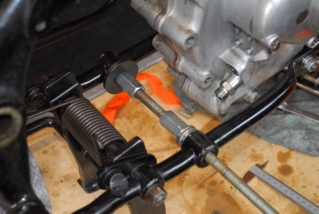 Bess has now been completely dismantled. Once the gearbox and engine plates had been removed, I did manage to address the problem caused by the missing spacers on the footrest bar. A length of studding and a couple of nuts was all that it took. I wound the nuts out carefully to force the bottom frame rails apart... checking the 'relaxed' distance frequently to make sure I didn't 'over do' it!
Having got the bike apart, the first job I tackled was to strip the front fork legs... for no other reason other than to try out the tool I made a few weeks ago that quite literally, pulls the legs apart. If you're interested in the tool and how I made it, look HERE. It worked remarkably well and I had both fork legs reduced to their component parts in a few minutes. At this point, I started to make a (rapidly growing) list of parts that needed replacing. Stuff like oil seals and the top bearing bushes. These were originally a hard, thermo-set plastic, like 'Bakelite' but bronze bushes are a better alternative for replacement. The stanchions are showing their age and have a little rust pitting but it's not bad enough to warrant replacement. They will be under the shrouds and not visible so I'll re-use them. The aluminium sliders are mechanically sound. All the threaded holes are good so they will just need a polish before being put back into service.
Having taken it all apart, I started to think about putting it all back together again. That means starting with the frame. I'm going to be a bit boring here and go for a traditional black finish. I've been in touch with a local(ish) company that specialise in stove enamelling and powder coating. The guy I spoke to seemed on the ball and was well aware of things like threaded holes and bearing surfaces that need protecting during the process. I'm going to see them in a couple of days to see what they can do.
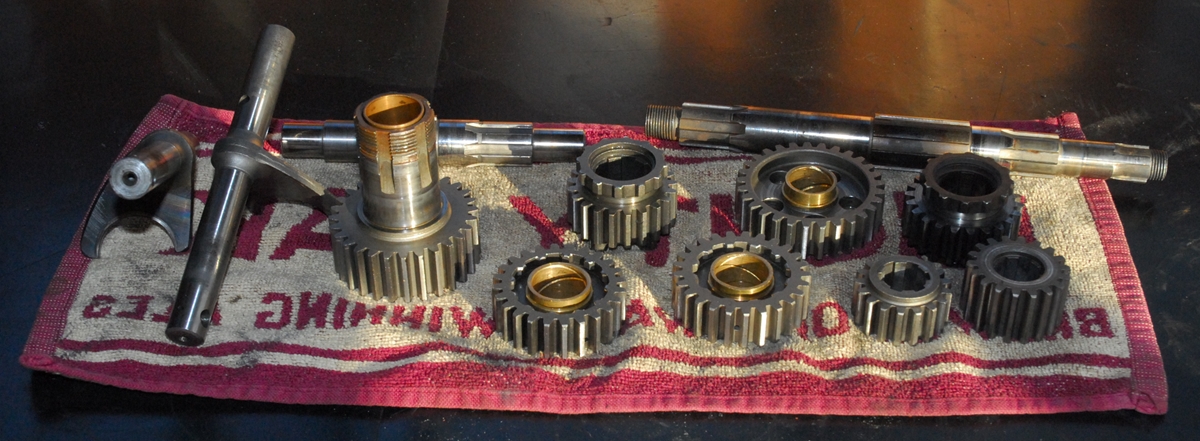
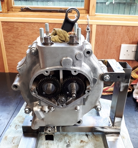
I'd been wondering about the gearbox. It's a Burman GB52 unit and was fitted to a number of British motorcycle marques. If treated well, they are pretty much bullet proof but it was well over 60 years old. It had been working when I last rode Bess and I briefly thought about not touching it. However, the last person to put it together had used a lot of black silicone sealant instead of the correct gaskets and quite honestly, it looked a mess. So it had to come apart. Just as well, really, the bloody stuff was everywhere. Having taken it apart, I found that with two or three exceptions, it was in very good condition. 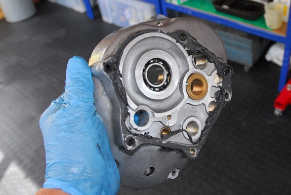
 There was no significant wear on the gear teeth and no appreciable sloppyness in the bronze gear bushes. There were some problems, however. It had been put together at some time in the past without the 5/16" diameter steel ball that should be fitted between the clutch operating mechanism and the clutch pushrod. This meant that the flat end of the pushrod had been bearing directly on the flat end of the clutch release thrust dowel. That increased friction had caused a LOT of wear in the clutch operating mechanism. The steel ball had subsequently been replaced but the thrust dowel hadn't. That wear was without a doubt, the cause of the problems I had when I replaced some of the clutch parts a year ago and had to make a longer pushrod. That badly worn part will be replaced, of course, and I will be able to revert to the standard pushrod. The only other parts that show any sign of wear are the two pins that locate in the selector cam and move the selector forks. They will be replaced as will the two ball races that support the mainshaft. They are ok but I've taken them out and will put new ones back. Parts like tab washers, split pins, oil seals etc. will all be replaced as a matter of course.
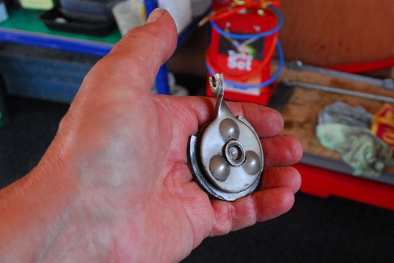
New parts for the gearbox have been ordered. Some have already been received but I'm still waiting for the bearings and I can't do much until they arrived. That being the case, I turned my attention to the 'Jampot' rear suspension units. 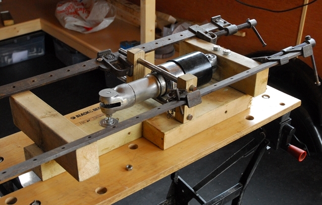 Both were leaking oil to a greater or lesser degree so they had to be sorted. Unlike the later Girling units that were fitted from around 1957, the Jampots can be disassembled and worn components can be replaced... If you can find replacements!!
On paper, it's a fairly straightforward job but like a lot of things, it's not always that easy in practice. Fortunately, I'd had previous experience with the same units on the Matchless G3 and had knocked up a couple of tools to help the process along. The units are held together with a large circlip but to get at it, the spring has to be compressed. That's were the first tool comes in... A bit 'Heath Robinson' but it works. With the sash cramps evenly tightened, the chrome ring is pushed up, compressing the spring and exposing the wire circlip. Once the circlip has been removed, the upper painted cover and the lower chrome plated cover can be slipped off along with the spring. The only real problem then is unscrewing the lower clevis from the main body tube. There's not a lot to hold on the aluminium body tube and you really don't want to hold it in a vice or use a pipe wrench like some people have been known to do. Either of those methods are likely to cause damage so I have another lump of hardwood fashioned to hold the body tube securely without causing damage.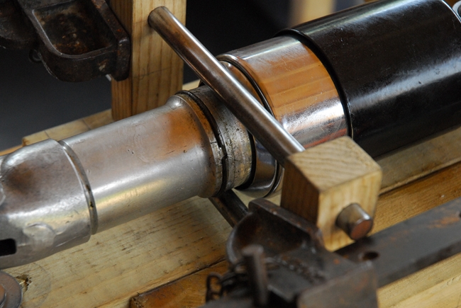 With the tube held securely, you invariably find that you still can't unscrew the lower clevis casting. It needs a little heat to expand it sightly. You can use a blowtorch but I prefer to use a hot air gun designed primarily for paint stripping. It supplies enough heat to expand the casting without the danger of an open flame in a workshop!!! Once the casting has been heated, I used a large open ended spanner edgeways on in the slot to unscrew the casting. That works for me.
Having got the units apart I found problems with both. As I said earlier, both units leaked oil, one worse than the other. The lesser leak was past the oil seal on the first unit. At some point in the past, a PO had held the inner steel tube with a vice or pipe wrench and had put gouges into the area of the steel tube where the oil seal operates. It was no wonder oil was leaking past. It looks like I'm going to have to fork out for a new tube. They are available but they aren't cheap. Bummer. The second unit had the worst leak and I soon found out why. The the thread in the lower clevis casting and it's mating thread on the aluminium body were damaged and a lot of the thread was missing.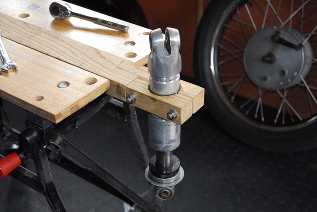 The PO had tried in vain to cure it by the application of copious amounts of some sort of sealer. It hadn't worked. The oil had leaked up the damaged thread and duly escaped. That is a potentially more serious problem. New lower clevises aren't available and usable second hand items are rarer than rocking horse shit. Double bummer. A year or so ago, the AMOC spares did have some new aluminium body tubes made. In fact, I bought a pair for the Matchless G3. They are still listed but there are none available at this point in time. Triple bummer!
I had a bit of a search round on the internet and have found a second hand lower clevis for sale in France. From the photographs, it looks to be in perfect condition but the price is high... Ouch! No such luck with the body tube but I have sent out an email or two to likely sources. Have to see what response I get, if any.
I've had another look at the suspect body tube and it may not be as bad as I first thought. I've cleaned up the thread and once the hardened sealer had been cleaned out I think it will be ok, particularly when mated up with a bottom clevis with a perfect thread. I've taken a fine oil-stone to the gouges on the steel inner tube and that has cleaned up satisfactorily too. With new top bushes and oil seals I'm fairly confident that we will have a pair of perfectly serviceable units.
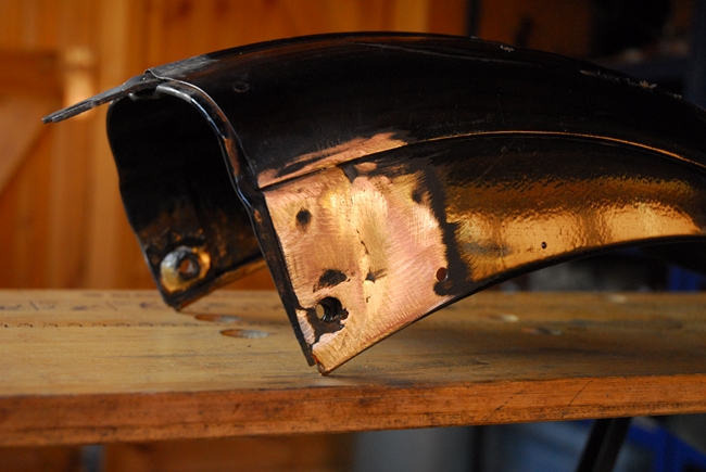
I've also worked on the rear mudguard as well, particularly the removable rear section. I've 'adjusted' the forked tang that attaches to the main section and the joint between the two parts is now much better than it was. I've also replaced the missing captive nut that the rear grab rail attaches to. That just left the split in the side valance to sort out. That really needed welding so I've entrusted that to Andrew (Jack) Russell, head honcho at CFS Fabricoat in Watton.
I've left the major frame components with Breckland Finishing Ltd for them to strip off the old coatings and give it all a fresh coating of gloss black. (Boring, but hey ho..).
The gearbox has been reassembled with no serious issues being found. The internals were all in excellent shape. As a matter of course, I've replaced the two ball races that support the main shaft, all the oil seals and locking tab washers. I've used correct new gaskets instead of the PO's liberal coating of black silicone sealer. The only other parts I've replaced were the two dowels in the ends of the selector rods that mate with the selector drum and the spacer behind the final drive sprocket that the oil seal runs on as the old one had a groove worn in it.
Bad news, good news, more good news, bad news. A couple of days ago I drove down to London. On the way, I called into T & L Engineering and dropped off the cylinder barrel and piston. They had a +.060" piston in stock and would bore out the cylinder to suit. So far so good... Next stop was into AMC Classic Spares to collect some parts that I'd ordered for the front forks; bushes, oil seals etc. Finally, in to see Ernie ("Otto Racs") and drop off some parts to be painted... the front mudguard, fork shrouds and Jampot covers..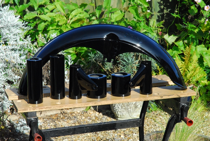
Bad news... Barry at T & L phoned and told me that they'd run a boring bar down my cylinder and they can't clean out the wear within the +.060" diameter. The good news, I guess, is that I now know that the engine's mechanical noise is almost certainly due to 'piston slap' with a +.040" piston running in a bore that was worn in excess of +.060". More good news is that the cylinder will now be re-sleeved back to STD. That's what I had to do with the Matchless G3 and it worked out very well. That engine runs beautifully and is as mechanically quiet as an engine of that design can realistically be. It will be more expensive, of course.... bad news. A little more good news is that some more bits I'd ordered from AMOC Spares and the replacement Jampot bottom clevis from France all arrived while I was away and were waiting for me when I returned home.
Just a quick update to keep my loyal reader happy. Ernie called to say that the front mudguard, rear suspension covers and front fork shrouds were finished and ready to collect. So I've been and collected them. He's made a fantastic job of them. All the surface blemishes on the 60 years old tinware have been removed and all parts now have a super glossy coat of black paint..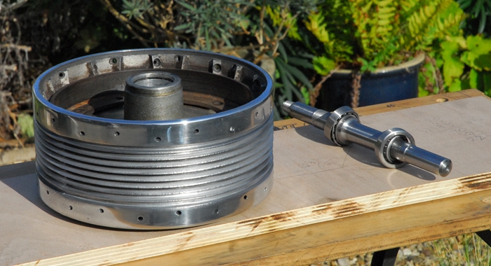
I've also collected the frame components from the powder coaters. They are still bubble wrapped and will stay that way until I'm ready to start the re-assembly but that will have to wait a while as 'life' in the form of a new kitchen installation has to take priority for the next couple of weeks. I have managed to take the old tyres off the wheels and the front wheel has been completely dismantled. The bearings were feeling distinctly 'rough' but I'd bought a new axle/bearing assembly from The Vintage Bearing Company some time ago and that will be installed in due course. I'll clean and polish the aluminium hub, brake plate and cover as best I can. I'm undecided whether to keep the old chrome rim or replace it with stainless steel as I have on my other bikes. The chrome is in good condition... it just needs the centre black and gold paintwork re-doing. Either way, I'll hopefully get CWC to rebuild the wheel and put a new tyre on.
 I have not been idle this last few days. The rear wheel has now been given the same treatment as the front. Unfortunately, whilst the chrome is in relatively good condition (I believe that both rims have been re-chromed at some point in the past) the edge of the rim has rusted through from the inside where it was in contact with the tyre bead. This means that using the rear rim is no longer an option. I'll get both wheels rebuilt with new rims.
I had a phone call from Barry at T & L Engineering yesterday to tell me that the cylinder barrel and new piston were ready for collection so I drove down to Elstow to collect them. I've also collected the rear mudguard back section from Andrew at CFS Fabricoat. The split valance has been welded and linished. Ernie will apply his magic when I take it down for painting and the repair will, I'm sure, be invisible. That's about it for now...
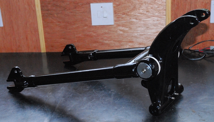 The new kitchen is almost complete and I was able to get into the workshop for a few minutes this evening. I've put the swinging arm back together with a new pivot pin, felt sealing(?) washers and new gaskets on the end covers. There is, perhaps, just a tad more wear on the bronze bushes than I would have liked but it is well within acceptable limits and doesn't warrant all the faff of replacing the bushes and then getting them line reamed.
I'll be taking the front hub over to CWC in a couple of days to have a new rim and tyre fitted. The rest of the tinware that needs painting will be taken down to Ernie this weekend when I'm going down to Ruislip for a couple of days.
Yesterday, I drove across to CWC in Coleshill. I still hadn't made up my mind what sort of rim I wanted. My other bikes have all had their wheels rebuilt with stainless steel rims, mainly for the low maintenance aspect... they don't go rusty. Bess, however, is not getting them. As I walked through the door, I finally made up my mind. She's getting top quality British chrome rims with the black and gold coach lines around the centre, exactly as she would have had when she left the factory. Nothing but the best for Bess!! They are also going to fit a new Avon AM6 "Speedmaster" tyre with new rim tape and a Michelin inner tube. It's only money and you can't take it with you. Ho hum...
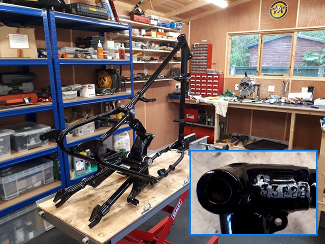 The rest of the tinware has been delivered to Ernie. The remaining parts for powder coating have been sorted, cleaned and labelled ready to be taken to Breckland Finishing later this week. So... what now? Well I've unwrapped the frame components and put them together on the bench. Not bolted together finally but with just a couple of studs in strategic places to hold it together for now. The frame has been given two coats... the first onto the prepared bare metal was a heavy zinc based primer for rust protection and finally, the gloss black. That adds up to quite a thick coating which will have to be removed in certain places that need to be a metal to metal fit. Not a difficult task with the Dremel and a box of sanding bands. I've removed the coating that was obscuring the frame number and given the area a couple of coats of clear lacquer to stop it going rusty. While the remaining parts are being painted / powder coated I can be getting on with reassembling the front end and getting the steering yokes and forks in place.
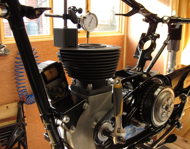
One of the things I wanted to check while I'd got Bess apart was the end float on the camshafts. The engine was, I think, a bit noisier than it should have been. Most of the mechanical clatter was from the loose fit of the piston but excessive end-float on the camshafts can also contribute to that clatter. I removed the timing cover and the camshafts. Everything was cleaned and put back together 'dry'. I'd laid a short length of fine solder wire on each camshaft between the gear and the cover. When the cover was fully tightened, the soft solder wire would be compressed and flattened. That done, the cover was removed again and the thickness of the flattened solder (effectively the end float) measured with a micrometer. It was 0.015" for both camshafts. That about 0.013" too much so I'll order some shim washers from AMC Classic Spares to bring the end-float back to 0.002" which should really help to reduce the engine noise.
 Measuring end float with flattened solder isn't an exact science but I figured it would be a good starting point. I ordered 4 shims from AMC Classic Spares, two at 0.003" and two at 0.010". They aren't cheap at £2 a pop and I didn't want to spend money needlessly. As it turned out, I still spent twice as much as I actually needed to. I put one 10 thou and one 3 thou on the exhaust cam and tightened up the timing cover. If there was still end float, I should have been able to spin the crankshaft but I couldn't. 13 thou was too much and the camshaft was jammed. I took out the 3 thou shim and tried again. This time the crankshaft spun freely. 10 thou it was then for the exhaust cam. The same procedure on the inlet cam and it was just one 3 thou shim that was needed. I had only needed one shim of each size so the remaining two will be kept for future use. While I was at it, I replaced the four cylinder base studs. I put a little "ThreeBond" sealer on each stud thread prior to screwing it into the crankcase. The tapped holes go all the way through and a little sealer would stop any oil seeping up the thread.
One last job today was to check the end gap on the new piston rings. Conventional wisdom says 3-4 thou. per inch of cylinder bore. The bore is 3.1/4" diameter which means a ring gap of 10 to 13 thou. The new rings were all at the top end with gaps of 12-14 thou but acceptable so they didn't need any material removing. Ideally, I would have liked the gaps to be a bit closer to the bottom limit as they will open up a bit as the rings bed in but they are what they are and you can't file metal back on. I'm sure they will be perfectly ok, assuming I can get the engine back together without breaking them!!
 Today, I spent an hour or three working on the frame. First off, I removed all the powder coating from the areas where four frame parts come together at the bottom of the aluminium swinging arm support. I wanted to ensure that when the frame was finally bolted together, there would be a hard, metal to metal contact. A little relative movement between the parts would wear the soft powder coat and the nuts could work loose over time. The frame is a bit 'flexible' as it is, being bolted up from a number of different components. Any looseness at the point where they all come together would be detrimental to good handling.
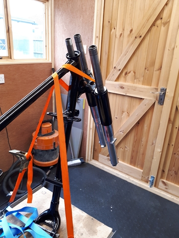
That done, I looked at putting the front end together. On paper, it was an easy job that I've done a number of times before on different bikes... this time, Bess... bless her heart... fought me all the way!! First problem came when I realised I'd missed out a component when I assembled the fork legs. A couple of days ago, I fitted the rubber 'spring buffers'. These are rubber bands, about an inch wide that are a very tight fit on the stanchion. 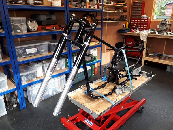 They stop the spring contacting the stanchion and rattling. There are three on each leg and they were not easy to get on. What I hadn't done was to slip the leather spring seating washer onto the stanchions before fitting the buffers. Now, of course, I couldn't get them past the rubber. Not a big problem, in the great scheme of things; I just cut across them at one point and then slipped them around the stanchions below the rubber buffers. They're captive between the stanchion and the chrome spring shroud and aren't going anywhere once the spring is installed. I probably made it a little harder for myself by deciding to fit the fork legs into the bottom yoke before fitting the yokes to the frame. In the end, it really wasn't too much of a problem. It was just a case of fitting the steering stem into the frame and supporting the assembly while the top yoke was fitted.... without loosing any of the 56 tiny steel balls that make up the top and bottom bearings. Ratchet straps are brilliant for that sort of thing. I just had to be careful not to damage the paint that Ernie had so painstakingly laid on the shrouds. All done now; adusted and tightened. Looking good, Bess!
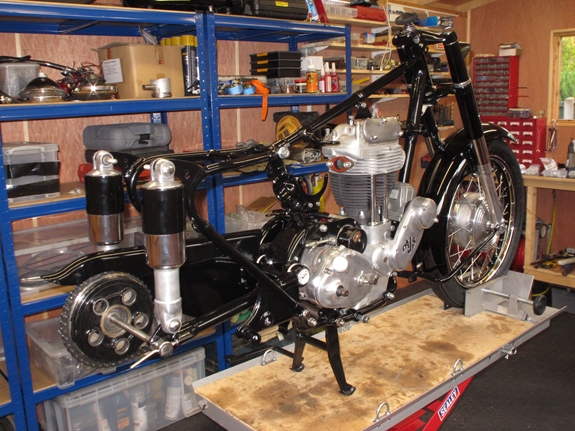
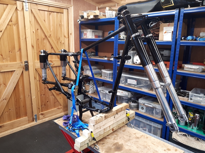 Now the front forks are in, it's time to turn her around on the bench. I've put new studs in the bottom of the sliders for the fork caps that secure the front wheel spindle and also installed the steering damper; correctly now and with the missing parts that the PO had omitted. The centre stand was the next job as it's very difficult job to fit once the engine and gearbox are in situ. If you've read "Part 1", you'll be aware that I've fitted a custom stand made by one of the AMOC members. I'd taken the angle grinder to it while it was off the bike. First, I've removed a slice off the top to give easier access to the engine plate stud that was being covered and second, I've removed a little from the areas that forms the 'stop' so that the stand is a little less 'upright' when deployed. That should improve the stability. I can't locate the spring until the right hand engine plate is fitted but with the front end up on blocks and tied down with a ratchet strap, she isn't going anywhere. The rear "jampots" had been mostly rebuilt earlier so all I had to do was fit the springs, shrouds and retaining rings, locking them all together with the circlips. Then it was just a matter of fitting them in place with new stainless bolts.
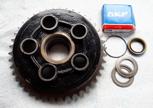 The rear wheel is of the "quickly detachable" type so I could fit the sprocket and rear brake to the rear fork. At least, that was the plan... Another little surprise from the previous owner stopped that in it's tracks. When I bought the bike, back in 2016, the vendor told me that he'd fitted a new rear chain and sprockets, and he had. The rear sprocket / brake drum was shiny and definitely new. What most definitely wasn't was the ball bearing that the drum runs on. It was as rough as hell and in dire need of replacement. Rather than put a new bearing and oil seal into the new drum, the PO had obviously knocked them out of the old drum and pressed them into the new one. They were rusty and the sealing washers showed evidence of serious misuse.. New components are now on their way from AMC Classic Spares. To be continued....
 The new bits from AMC Classic Spares turned up around mid morning so no excuse not to get on with it. The new bearing went into the freezer while I finished my coffee and biscuits. The new bearing is of the shielded variety which means that it will be pretty much maintenance free. The drum/sprocket had been cleaned thoroughly and went into my brand new oven at 200°C. Thirty minutes later it came out again, as did the bearing from the freezer. I would like to say that the bearing just dropped into place but today, my luck wasn't that good. The washer went in first, then the bearing... only to jam halfway in. Not really a problem as a couple of big washers, a length of 12mm studding and two nuts pulled it into place. Once the second washer, circlip and oil seal were in, the brake plate was put back into place and the whole assembly offered up to the left side of the rear fork. I had to clear the powder coating out of the axle location to allow it to fit but I expected to have to do that.
Things are progressing. I've collected the last of the powder coated bits from Breckland Finishing and very nice they are too. The coating from here seems to be thicker and glossier that it did from CWC where I've had stuff done before. Talking of CWC, I've also collected the rebuilt front wheel from them and dropped off the rear hub for similar treatment. The front hub has been built up with a new chrome rim which has been coach-lined as it would have been back in the fifties. It is also sporting a new Avon Speedmaster ribbed front tyre. Not everybody's choice, I know, but it's "period" and made from modern rubber compounds, they handle well enough for an ungainly lump of old Brit Iron.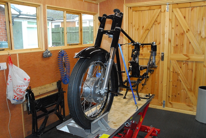 The new front axle and bearings from the "Vintage Bearing Company" were installed without any problems as I had all the "tools" I needed. That said, I did hit a snag that has stopped me fitting the wheel into the front forks. An important nut is too tight on the thread cut into the new axle. It goes on a few threads but If I tried to force it any further, it may well damage the thread on the new (and very expensive) axle. It's the nut that sets the position of the front brake plate so it has to be right. The other nut that goes on the same thread fits perfectly so I believe it is the tight nut that is at fault. It's a very thin, 3/4" x 26tpi, nut and not something that you're likely to pick up in the local hardware store. My usual source of supply, the AMOC Spares shop have none in stock so I've ordered a suitable tap from Tracy Tools and will run that through the tight nut when it arrives. That should sort out that little problem.
Things have been happening... The tap I ordered from Tracy Tools arrived the day after I ordered it (thank you Tracy!). I ran it through the recalcitrant nut and I'm happy to report that the nut now spins down the thread on the new axle with ease. That meant that I could assemble the front brake plate to the hub and put the front wheel back between the fork legs. That also meant fitting (carefully) the newly painted and very shiny front mudguard along with the front stand and the brake torque arm. The whole lot went together without a hitch, thankfully. With the front wheel in place and securely clamped on the work bench, the wooden blocks that had supported the frame were removed. Now I can think about getting the bottom end of the engine installed sometime in the not-too-distant future.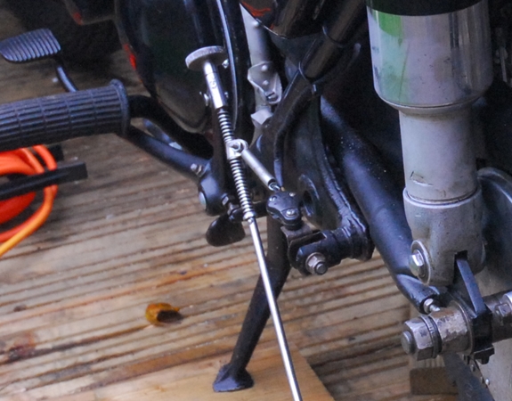
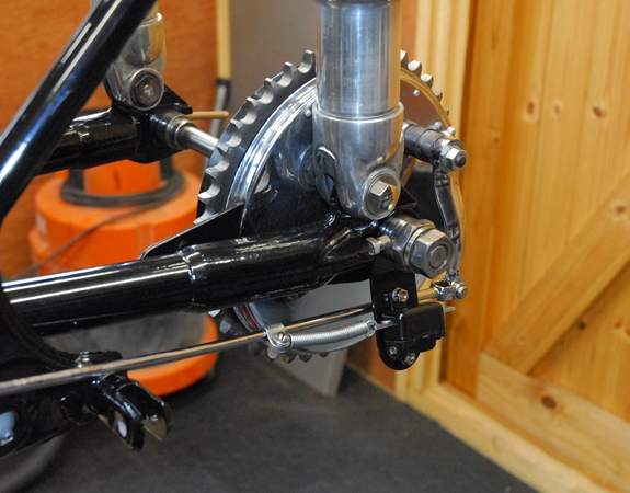 While on the subject of brakes, the rear brake light switch had been bugging me for some time so today, that was sorted as well. The switch that the PO had fitted wasn't the correct item and it certainly hadn't been fitted in the approved manner. It was screwed to a piece of rusty bent steel which was in turn bolted to the pillion footrest mounting post. That has now been replaced with the correct switch and mounting plate which is secured on the rear axle.
 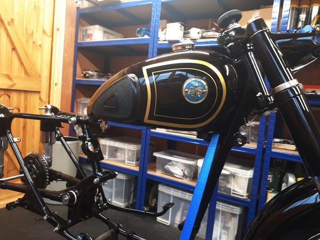 That looks a little less of an after-thought (but if I'm being truthful, not much!). However, that's the way it was fitted when it left the factory so it's good enough for me.
Just a little more work carried out today. When I had the tank painted a couple of years ago, I didn't have the correct knee grip mounting plates and the rubber grips were cheap foreign reproductions. They didn't fit very well so I thought that in the short term, I'd attach them to the tank with some strong double sided adhesive tape. That worked for a short while then the tape started to let go and it didn't look too good. Now that I'm rebuilding Bess, it was time to correct that so I've obtained a pair of good quality, British made, knee grip pads and a pair of the correct mounting plates, all from AMC Classic Spares. It should have been an easy job but it took a little longer than I expected. The remains of the old adhesive tape needed to be cleaned off and the tapped holes in the tank needed a bit of cleaning out before the attachment screws could be screwed in to the full depth. Also, the mounting plates needed a little 'adjusting' before I was happy with the way the pads fitted. On the whole, though, I'm pleased with the way they now fit so I guess they were worth the expense.
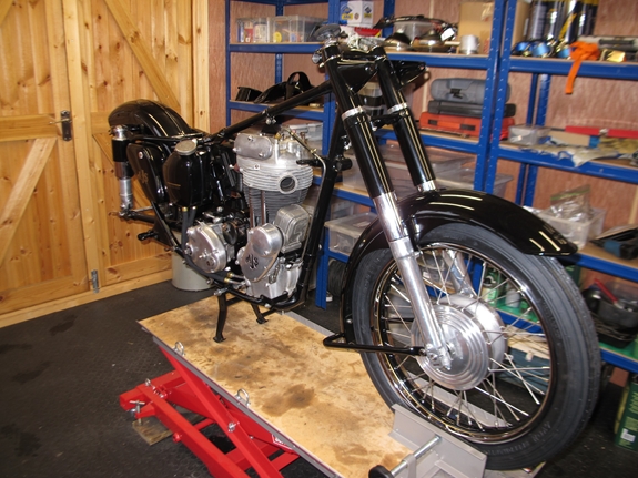
Today was a good day, well, sort of, anyway. The bottom end of the engine went back into the frame without any issues. The magneto, on it's mounting plate, utilises the front engine plate studs and it wasn't until I'd got that all bolted into place that I realised that the four screws holding the magneto to the mounting plate were only done up finger tight so it all had to come off again!!. 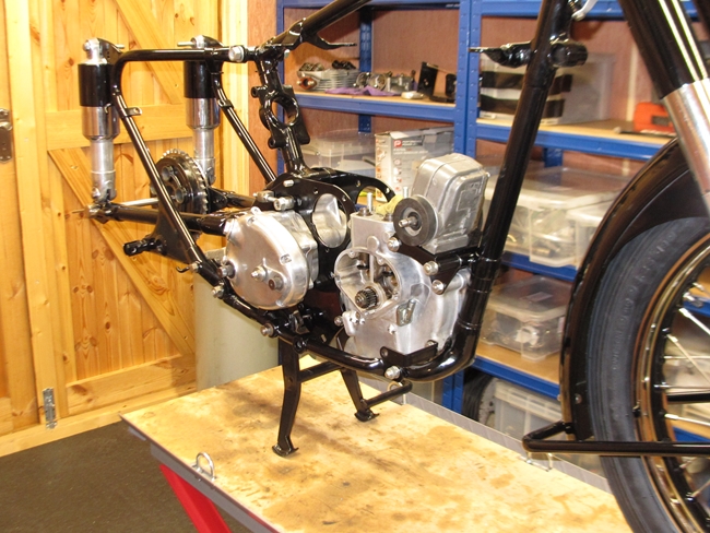 On the subject of magnetos, for them to work, there needs to be a complete electrical circuit for the secondary HT coil or you don't get a spark. What this means in a practical sense is that the magneto body need to be connected electrically to the engine. However, the powder coating on the mounting plate, engine plates and frame is a very good insulator. Rather than scraping it off to get a 'metal to metal' contact, I've used a short length of cable to connect one of the magneto mounting screws to the front crankcase stud to give a good, reliable electrical circuit. Having sorted out the magneto, I fitted the right hand rear engine plate as it is that one that the end of the centre stand spring is hooked onto. As usual, the spring fought back hard but I prevailed... and then I found out that I couldn't get the gearbox in so the plate had to come off again. Are you seeing a pattern emerging here? Eventually, the two rear engine plates were in place with the gearbox between them but not secured. The top gearbox mounting bolt I found and installed but could I find the bottom mounting stud? Could I hell! It's in the workshop somewhere because I took it out a few weeks ago and I haven't thrown anything away, but a thorough search of all the boxes I stored parts in failed to find it. I've ordered a new one, but you can bet that the day the new one arrives, the old one will turn up in the most obvious place! Don't you just hate it when that happens. One of these days. I'm going to have a serious word with the "shed pixies" that insist on moving my stuff about!!
 The new gearbox mounting stud arrived this morning, along with a few other bits and pieces that I'd ordered so no excuse not to get on with things. Having put the new stud into place, I have to say that it is just a bit on the short side. I'm going to have to use a couple of thin nuts... but I need a thin nut on the left hand side anyway as a full nut will foul the centre stand so I've added them to the order I'll be placing with Motalia. With the gearbox now secured, I could fit the rear chain guard and final drive chain. It's much easier to do that now before I get the primary drive chaincase on as I have easy access to the final drive sprocket on the gearbox. So... the rear chain is now on and joined with a new split link. I don't like using these links again once they've been taken off.
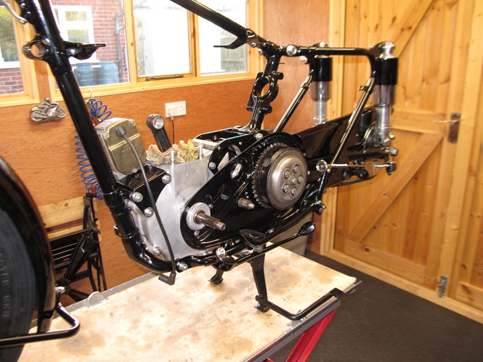
The next job was to put the rear half of the primary drive chaincase in position. This was attached with slotted head screws which were incorrect. It's now secured with the correct thin hexagon headed set screws and also the correct tab washers to make sure they won't come loose. With the back half of the chaincase on, I could build up the clutch and get that on. There are 24 loose 1/4" diameter steel rollers that make up the bearing for the outer clutch drum. I'd been very careful to keep these safe as they are easily lost. I carefully washed them in a pot of white spirit and emptied them out into my hand... turned around, hit my elbow on the pillar drill table and shot the rollers all over the work bench. "Oh dear!" I said... or words to that effect. 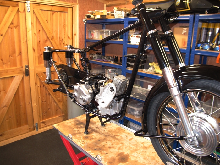 22 of them I found easily but it took me another half an hour to find the final two. They had dropped into a box of disposable nitrile gloves!! By now, my loyal reader, you will have realised that things are not going quite to plan... In fact, it's been one cock-up after another this last few days. Ho hum. Having found all the rollers, the clutch assembly went back onto the gearbox mainshaft with any further mishaps. I've used a new nut and tab washer to secure the clutch onto the mainshaft; the nut being tightened with the air operated impact driver.
One last job today was to install the camshafts and sort out the valve timing. That was straightforward enough, it's just a case of lining up the dots on the cam gears correctly... or in this case, incorrectly as I've deliberately timed this 500cc engine using the 350cc engine timing dots. This advances the inlet cam timing by one tooth on the gear (or 18°). "Why?" I can hear you ask. Well, I'd asked a well respected engine guru why the 350 engine inlet cam timing was more advanced than the 500cc. His reply was that it was the other way round. The 500 engine's inlet valve timing had been deliberately retarded to make it more tractable and better suited to pulling a sidecar. If I wasn't hauling a sidecar and wanted a little more performance, I could use the 350 timing marks. So I have!! That just left the timing cover to fit, ensuring that I'd got the shim washers that I'd sorted out a couple of weeks ago in place. New screws were used as the old ones were showing signs of wear on the screwdriver slot. Finally, a couple of things to note... A new footrest rod has been installed along with the three spacers between the rear engine plates and the frame that the PO had, for reasons best known to himself, omitted. The prop stand has been put on and as I surmised up the page aways, with the new clutch operating mechanism in place in the gearbox, I could use the correct length clutch pushrod; not forgetting to drop in the 5/16" diameter steel ball that had been left out previously. Right... "Time for bed", said Zebedee, or in my case this evening, a dinner date with my ex-wife's older sister.
 Another day, more jobs to do. Time to start getting the engine back together and unsurprisingly, the first problem. The new gudgeon pin that came with the new piston was a couple of tenths of a thou. bigger in diameter than the bore in the little end bush. It wouldn't fit and I didn't have a 3/4" diameter reamer. What I did have was the oversize piston that I'd taken out. That was new when I bought the bike so it had done less than 1,000 miles. The gudgeon pin from that piston was a perfect fit in the connecting rod. It was also a good sliding fit in the new piston so the new piston was installed with the old gudgeon pin. Having sorted that out, the re-sleeved barrel was slipped over the piston and dropped down onto a new base gasket. New nuts secured it to the crankcase.
Having sorted out the valve timing yesterday, I was now about to sort out the ignition timing. The magneto is chain driven from the exhaust camshaft and needed to be set in the correct relationship to the crankshaft. I went into the procedure at some length in 'Part 1' of the AJS M18S saga so I'm not going to repeat it all here. When the bike was made, in the 1950s, the correct ignition timing was 1/2" B.T.D.C. at full advance but with modern lead free and alcohol dosed petrol, the general consensus is that it should be retarded slightly; 7/16" B.T.D.C. being frequently quoted. In the end, I settled for roughly half way between the two. With the timing set and the chain sprockets secured, I put a spark plug into the magneto's plug cap, rested it against the crankcase and turned the engine over with a spanner on the crankshaft. The result was a good, fat spark. Happy days.
It's a 'finish off' day, today. I started with the dynamo and primary drive. That all went back together without any issues. Then it was the top end of the engine. The cylinder head, had already been cleaned up, had the valves lapped in and a correct set of springs fitted. There are three different sets of 'hairpin' valve springs that could be fitted... Springs with 3 coils and a lighter gauge of wire, which are for the lightweight 250cc/350cc engines. Springs with 4 coils of the same gauge wire which were fitted to the pre '57 heavyweights (and which were originally fitted to my 500cc heavyweight). The third type are springs with 3 coils of a heavier gauge of wire which were fitted to the later 'short stroke' engines (and are now fitted to Bess). Very confusing because they all look pretty much the same.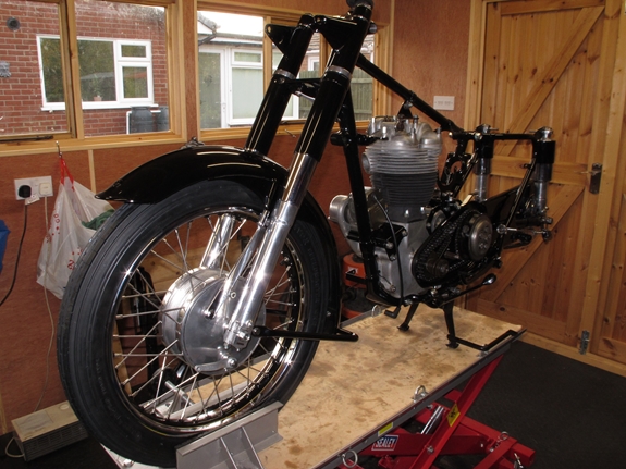
 Anyway... the head was bolted on with a new copper gasket and new rubber seals on the pushrod tubes. The bolts were tightened down to 35 ft/lbs with a torque wrench. The pushrods and rocker box went on next, again, with a new gasket. With the head steady in place, there were just a couple of small brackets to fit and that was it. I can't do much more until I get the rear wheel back from CWC and the tinware back from Ernie.
It's been a few days since any appreciable work has been carried out on Bess. However, I now had the rest of the tinware back from Ernie so it was time to start again. The rear mudguard was the first thing to put back. That went on without any problems. The oil tank was next, along with the battery carrier, closely followed by the two tool boxes. Then I turned my attention to the primary drive cover. I had a new 'T' section rubber sealing band from the AMOC Spares shop which is a big improvement over to old 'U' section band that was fitted originally. With the bike high up on the hydraulic work bench, the cover, rubber seal and aluminium clamping band went on with only a modicum of hassle.
 That just left the oil pipes (or so I thought). I'm not really sure whether I've been really clever or really stupid with them. I wanted them to look neat but be secure at the same time and I don't think 'Jubilee' clips look neat so I've done something a little different. The steel pipes at the bottom of the oil tank for the feed and return oil are 1/2" diameter, as are the short copper pipes that are connected to the engine's crankcase. Conventional wisdom is to use lengths of 1/2" bore rubber hose and secure them to the metal pipes with either crimped ferrules or some variation on the Jubilee clip theme. I don't possess a crimping tool for large ferrules and I don't like Jubilee clips, so... I found some braid covered rubber hose, suitable for oil and petrol, with an 11mm bore... That's about 7/16" in old money.
 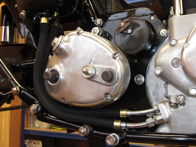 I also acquired four brass ferrules that were a tight fit on the outside diameter of the hose from the same supplier. If I could persuade the 7/16" bore hose to fit over the 1/2" diameter metal connections, with the ferrules in place, I reckoned they would be a tight enough fit to be oil tight... particularly as there is no pressure to speak of in either the feed or return lines. It was a struggle as the ferrules kept the rubber compressed but in the end I won and the pipes are on. It remains to be seen if they are secure enough. I will have to keep a careful eye on them when the engine runs and the oil gets warm for the first time.
Not sure why, but as I walked around the back of the bike to admire it from another angle, I gave the rear sprocket a poke, expecting it to turn... It didn't. Further poking revealed that the primary drive inner case was hard up against the chain on the gearbox sprocket... and I'd just spent half an hour on fitting the outer cover. Why hadn't I checked that?? Fortunately, it wasn't a very big deal in the great scheme of things. Outer cover off again, the 7/16" stud removed and a couple of 7/16" washers between the rear chaincase half and the spacer tube. With the stud back in again and secured, the case was clear of the chain. All I had to do was put the outer cover and seal back on again.
Things are progressing slowly. The more observant of you will notice that the handlebars, control levers and cables are now in place, as is the carburettor, twistgrip and air slide lever. All very simple, eh? Well no, actually, it wasn't as straightforward as it should have been. I'd ordered some new stuff to replace the old control levers and cables. In most cases the quality of the replacement parts is not very good. 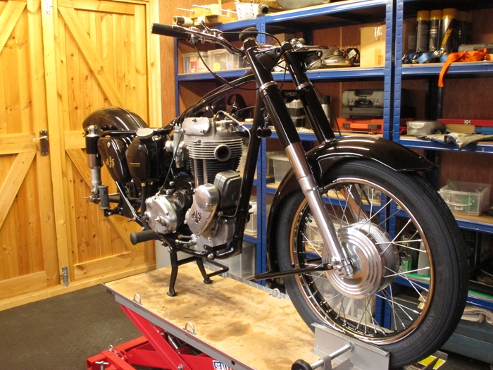 The clutch and brake levers are just about acceptable and will do for now but in the longer term, I'll look for some better quality items. The twistgip, although advertised as "high quality", was total rubbish. I've cleaned up the old original Amal item and will keep that. The cables (clutch, front brake and valve lifter) I bought from AMC Classic Spares but none of them fitted correctly straight out of the box. The nipple on the brake drum end of the new front brake cable didn't fit the yoke/clevis on the brake arm. The inner clutch cable was too long and the adjuster was only in the gearbox by a couple of threads. The valve lifter inner cable was plenty long enough and took up nearly all of the available adjustment to get it set correctly.
Amongst my collection of bits and pieces, I have a number of cable sleeves and adaptors. I used one to good effect on the valve lifter cable. Not only did it mean that the adjuster wasn't fully used but it actually fitted the lifter lever on the rocker box better as well. That was a result. Having emailed Steven at AMC Classic Spares, I've found out that the yoke/clevis on my front brake actuating lever is 'not a standard fitting' so I couldn't use the 'standard' cable. Unfortunately, it seems that a replacement 'standard' part isn't available from any of my usual sources so for the moment, I've put the old cable back on. Why the clutch cable doesn't fit as it should is a bit of a mystery. Steven says that it should be fit perfectly and the reason why it doesn't must be down to wear in the mechanical operating parts in the clutch or gearbox. As I've replaced all the worn parts with new items, I'm not sure how that can be the problem. Ho hum... I expect I'll have to modify the cable by shortening the inner bowden wire and soldering on a new nipple.
Only a couple of other things... The pillion footrests have been put on with new rubbers and I've cut a piece of steel plate to fit under the saddle where the old mechanical voltage regulator was originally fitted. I'll use this to mount the newer, solid state DVR2 regulator and the flasher relay. I've decided to keep the electrical system as it was originally i.e. 6 volt, positive ground.
I 'phoned CWC to enquire if there was any progress being made on the rear wheel. It would seem not. Apparently, the elderly gent who does the coach lining is unwell and has been for a number of weeks. They were uncertain when he would be able to resume work but thought it may be soon. Until my new rim has been painted, it can't be built up onto the hub so it doesn't look like the rear wheel is going to be ready any time soon.
 Time has moved on and left me behind, I'm afraid. I've bought a few bits and pieces to help get things moving again. First off, I bought a new clutch cable kit from Venhill. I wasn't happy with the way the cable I bought from AMC Classic Spares fitted. The inner cable was a little too long and the whole thing was a little too short to route the way I wanted to do it. The Venhill cable was much heavier construction and has a Teflon liner. All I had to do was cut the inner and outer to length and solder on a nipple at the handlebar end. I'm very pleased with the result. I've also bought a set of indicators which I hope will not look out of place. They were matt black when I bought them but have now been given a coat of gloss black to match the rest of the bike. The two at the front will mount each side of the headlamp and will be used to secure the headlamp shell between the fork shrouds (with the aid of some brass bushes to take up the clearance). The two at the back will be fitted on either side of the rear mudguard, where the grab handles fit.
The piece of steel plate I cut to mount the voltage regulator etc. on has been drilled for the various components and painted black. This morning, that was bolted into place under the saddle. The regulator, electronic flasher unit and horn relay have all been attached. There is also a brass screw to act as a connection point for all the red, ground return wires.
Progress is... well, progressing. The mechanicals have pretty much been completed now. I'm only waiting for the back wheel from CWC. I wasn't altogether happy with the front brake. There was plenty of 'meat' on the linings but there was still a lot of movement on the actuating lever so I've had the wheel out again, stripped out the brake plate and put a couple of packing washers behind the thrust pins. These would have been fitted at the factory but have been lost sometime over the last 60 years. That improved the 'feel' of the front brake no end!
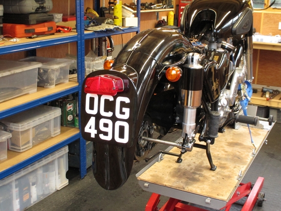 The removable section of the rear mudguard, complete with number plate and rear light, has been temporarily attached. I have to say, I'm impressed with just how well the two parts match up at the joint... something that 'bugged' me from the moment I first clapped eyes on the bike. That's partly down to me 'adjusting' the metalwork and partly down to Ernie's expertise with filler and paint. I doubt it was any better than it is now when she first left the factory in Plumstead. Anyway, time to get on with the wiring. Some of the harness I made a couple of years ago can be utilised but mostly, she will be rewired from scratch. I've added indicators with the associated handlebar switch and electronic flasher unit which has added to the complexity. As the indicator switch is not automatically self centring, a warning lamp is essential if I'm not to forget to turn them off. As Bess has the large, faired headlamp shell, there is plenty of room for a warning lamp to be fitted between the ammeter and the light switch. I've also blown the budget completely and bolted on a Lucas "Altette" horn, the same as the one on "Alice". As this draws a considerable current from the battery, a relay has been included in the circuit.
 More delays, I'm afraid. Christmas and the New Year have passed and Bess is still up on the workbench without a rear wheel. I'd left the rear hub with CWC back in October, expecting a turn-around of approximately 5-6 weeks. That never happened because the gentleman who CWC employed to do the pin-striping had been admitted to hospital for surgery. CWC's best estimate was early in the New Year. I telephoned a couple of days ago and was told that it would now be mid February as they had no 19" rims and weren't expecting supplies for at least 6 weeks. That left me with a problem as I needed to get Bess off the workbench. Fortunately, a member of the AJS & Matchless Owners Club who lives a few miles away in Boston has come to the rescue and lent me a rear wheel. Thank you, Steve. Now I can move Bess back into the garage.
Progress at last. It's St. Valentine's Day, mid February and somebody loves me. I phoned CWC to find out the latest on my rear wheel and was told that it was ready for me to collect... finally!! I've made arrangements to collect it next Wednesday morning, prior to meeting up with Rob, Les and possibly Tractor Dave for a pint or two and a bite to eat at the George & Dragon in Stoke Golding. 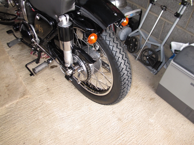 Unfortunately, I'm going to have to get Bess back into the workshop once the wheel is in as she's haemorrhaging oil at an unacceptable rate of knots. At this point in time, I'm not exactly sure where it's coming from. It could be leaking from the gearbox or it could be one of the new oil pipes. That's what I will have to find out.
Move on a couple of weeks. I've collected the rear wheel from CWC (and enjoyed a pint and a sandwich with the lads. I don't get to see them often enough now I've moved up to Lincolnshire). CWC have finally finished it and I guess it was worth the wait. The new coachlined chrome rim with the new tyre fitted is the business. It has been fitted back into the rear fork and looks good.
Bess is still leaking oil... It will have to wait for a while as the new G80CS is in the workshop and up on the bench. She's nearly finished, only needing the seat renovating and two new tyres. Hopefully, I'll get Bess back into the workshop and fixed in time for some early summer riding.
Move on another month or so. It's best part of the way through March, 2020. The Coronavirus pandemic has us all in it's grip and we've been advised to stay at home... so no better time than now to sort out the oil leak. Bess is back in the workshop and on the bench. I've stripped off the exhaust pipe and the left footrest. The oil leak appears to be coming from the gearbox... more specifically, from around the gear change shaft. 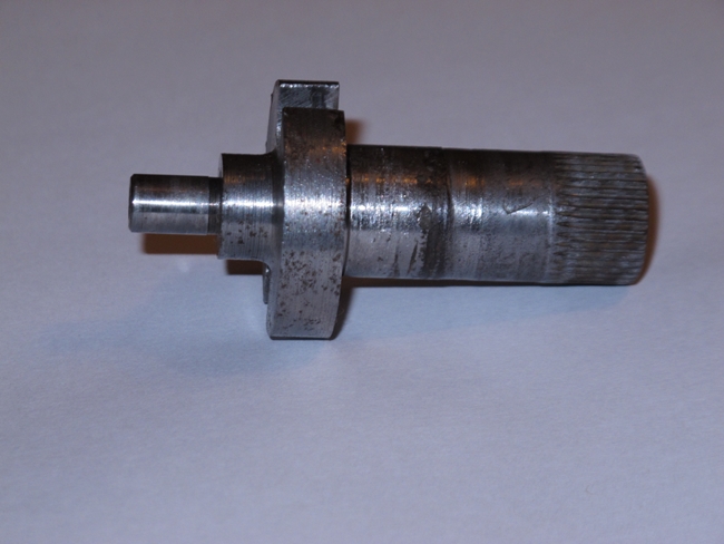 Oh yes... the more observant and knowledgeable amongst my readers will already have noticed what I am about to admit. Go up the page a ways and have a look at the photo of the nice new oil pipes that I've put on. If you know anything about heavyweight singles, you will see immediately that I've put them on the wrong way round. The 'return' connection on the oil tank is connected to the 'feed' side of the oil pump. Silly, silly boy!!!
Having removed the oil pipes and the gearbox outer cover, it was the gear change shaft that I wanted a closer look at. It's not in the best of conditions, unfortunately. It's worn and scuffed exactly where the oils seal sits. Finding obscure parts for a 65 year old gearbox is never easy but I've managed to find a "new old stock" replacement shaft from a classic bike place in Holland. It's being shipped over, air mail. A new oil seal and gasket are coming from the AMOC spares department. When I've got all the bits, I'll put it back together again and this time, put the oil pipes back on correctly.
The NOS gear change shaft turned up today. It was grubby but perfect once I'd cleaned all the old protective grease off. It had probably been that way for the best part of 70 years. With that cleaned up, I assembled the outer cover with a new oil seal. It was a good, tight fit which bodes well for keeping the oil inside and not letting it dribble out. A new gasket, with a little Hylomar Blue sealant, was fitted and the outer cover screwed back onto the gearbox. I filled it with fresh SAE50 oil... No oil leaked out from around the gear change, so that's that! I'll sort out the new oil pipes over the next few days.
The oil pipes have been replaced correctly and the last job, putting the removable section of the rear mudguard back on, has been completed. I've attached a new reflector to complete the job (and comply with current regulations). That's it for now. I've started the engine and checked that the oil returns to the tank as it should. There's still a bit of a rattle coming from the engine... more than I would like, if I'm honest, but I'll see what it's like when she's run for a while and up to temperature. That will have to wait until the coronavirus restrictions on un-essential journeys have been lifted. Ho hum...
It's no good, I can't wait any longer. After four weeks of being under virtual house arrest, today I went for a short ride up to Gedney Drove End and back. Bess started readily enough and we shot down the road, only to turn around and come back again... The speedometer wasn't working. I thought that maybe I'd not connected the drive cable at the rear wheel but that was securely in place. I ignored it and took off again. The 13 mile trip was fine... Bess ran beautifully. In fact, bearing in mind that she'd been re-sleeved and had a new piston, I had to hold her back. The odometer faithfully recorded the distance we'd covered but the speedometer needle stubbornly stayed at zero. When I pulled up on the drive, there was a few drips of oil from the engine breather. I'm hoping that once the new piston rings have bedded-in, there will be less pressure in the crankcase and consequently less oil being pushed out of the breather. I've taken the speedo off and will send it off to Russell at Chronometric Instrument Services tomorrow. Ho hum...
OH, YES... The speedometer has been refitted and this evening, Bess and I went for an 80 mile run down to Huntingdon and back. She ran like a dream... Bearing in mind that she has a re-sleeved barrel and a new piston, there was no sign of any tightening and she revved freely enough. We cruised at around 55 mph with an occasional burst up to 65. The advanced inlet cam timing and the increased inlet valve lift that the modified rocker assembly has given, seems to have paid off. The engine pulls strongly and I have no doubt that when fully run in, and with the slightly raised gearing she now has, 80 mph will be easily achievable and possibly even more under favourable circumstances. All is well in my world!!
Wednesday, 19th August, 2020 I've put around 500 miles on the clock now, including a couple of runs down to the Strathmore Arms in St. Paul's Walden, near Hitchin. Bess has behaved impeccably. There has been no sign of any tightness in the bore and no smoke from the exhaust. Keeping up with 70mph traffic on the A1 dual carriageway has been no problem, with a fair bit still in hand for overtaking. When she's fully run-in, and I can really give her some beans, she'll be a right handful.
OK... let's move on three months. It's now the beginning of November. When I last rode Bess, a few weeks ago, I suspected that not all was well with the indicators. They were purchased from a well known purveyor of such items and I thought they suited Bess well. However.... There's always a "however" with my stories... It seems that the vibration of a big single was more than the somewhat flimsy bulb holder could take. It had snapped off. On further investigation, it appeared that of the 12 such indicators I've fitted to 3 different bikes, 7 of them had suffered the same failure. All of them on two of my AMC singles. They seemed to cope better with the higher frequencies generated by the little Triumph Tiger 90 and none of those had failed; but in truth, I haven't ridden many miles on her since I changed her over to this style of indicator. Time for a re-think so Bess was brought back into the workshop.
I'd chosen these particular indicators because they were relatively small, black, took a 'standard' BA15s bulbs and were at the cheaper end of those available.(Yes, I know... You get what you pay for.) I looked at what was available again. Most were LED and only suitable for 12v systems. (Bess and Alice are only 6v). If you look back at the story of "Alice", you'll see that I'd fitted indicators that were replicas of the ones originally fitted to my Triumph Bonneville. They were much more robustly made but they were bigger... and chrome plated. They looked just bit, well, brash and out of place on an all black bike. I could change that, the colour anyway, so I bought a new set for Bess, scuffed up the chrome plated surface and sprayed them black. The mounting stalks were deemed unsuitable so new mountings were fabricated from 2" (front) and 3" (rear) long, 5/16" UNF bolts with 4mm holes drilled through their length for the cable and some 16mm black acetal rod. Thank you Mr Myford, I couldn't have done it without one of your lathes.
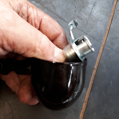
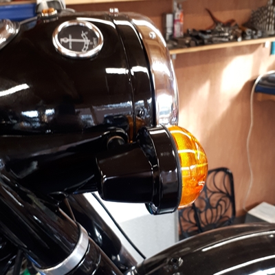
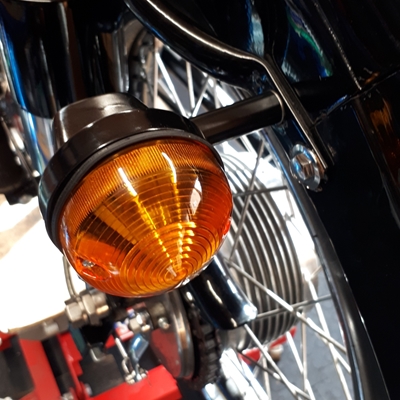
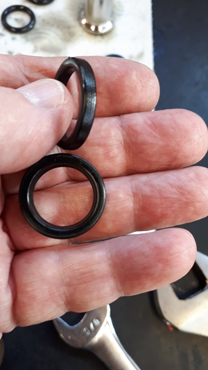
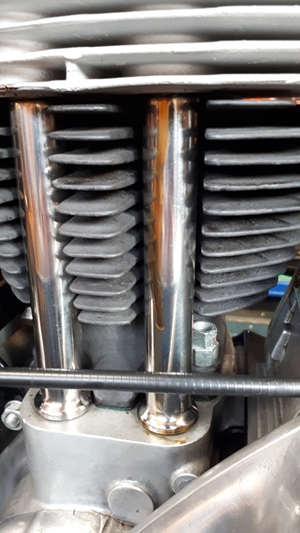 What idiot said "Owning old Brit Iron is Fun."? Whoever it was had obviously never owned one. Having sorted out the indicators, and, incidentally, having fitted a two pin charging socket under the saddle to allow the battery to be connected to a maintenance charger over the winter, I took Bess out for a short run. Perfect... all was hunky dory. Or so I thought until I arrived back home and found that the top of the crankcase was covered in hot oil. Bugger... What's happened now? A quick wipe down and it was obvious that oil was running down the outside of the exhaust pushrod tube.
When I rebuilt Bess over last winter, I followed the advice given by some on the AMOC forum and used BS210 o-rings (4 on each tube) instead of the prescribed solid rubber oil seal at the top of both pushrod tubes. It would appear that those o-rings had failed... dramatically.
An hour later, I lifted the head and both pushrod tubes just dropped out. They weren't being held by the seals at all. Then the seals dropped out. They were very hard, and very definitely not the same shape as they were when I installed them. Square section o-rings tend not to seal very well, it seems. My fault.... I had bought Nitrile o-rings. What a mistake-a to make-a. The heat and oil had affected the Nitrile rubber. The o-rings had hardened and deformed to the point where they were no longer seals. I have now ordered the Viton equivalents (higher temperature tolerance and better resistance to oil) and will re-assemble in due course. So... If you're thinking of doing the same, make certain that you buy the Viton o-rings and not the cheaper Nitrile ones.
The new Viton o-rings arrived this morning, so I've reassembled the engine. Putting the tank back, I noticed that there was petrol dripping from one of the rubber fuel lines. It seems that the hose that was supposed to be suitable for alcohol doped petrol wasn't. Ho hum... Rather than buy some more from the internet, I bought a length from my local Halfords. The guy assured me that it was the correct stuff and I would have no problems. Guess we'll have to wait and see. I may take this opportunity to change the fuel taps, ("petcocks" if you're American), as the "push on - push off" slide variety that are currently fitted aren't the easiest to use with gloves on. I'll look at getting a pair of lever operated taps. They are easier to turn on and off with gloves on. If you're giving the old girl some beans down the A1 and you have to go onto "reserve", you don't need to be fumbling about under the fuel tank trying to work out which way to push the slide!
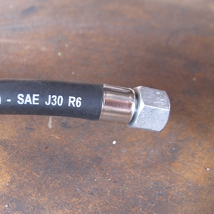
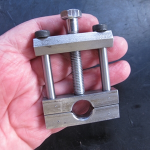 I'm not a great fan of using "Jubilee" clips to secure fuel hose. If you over tighten them, they can cut into the hose and that's never good. So... as I have to make up a new set of petrol pipes for Bess, I'm going to use crimp ferrules as they did at the factory. With that decision made, I ordered the ferrules and the crimping tool from a well known motorcycle dealer on-line. They turned up a couple of days ago. The ferrules were good. They fitted the hose I'd got perfectly. Unfortunately, the crimping tool was just so much rubbish, I sent it straight back to the dealer for a refund. I decided that I would make my own. After all... I was an engineer in a previous life.
 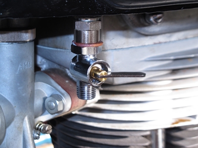 A bit of furtling about in my scrap material box and I'd found all I needed. This morning I spent an hour or two with the pillar drill and my lathe to produce a crimping tool. I have to say, I'm quite proud of it and what's more, it works perfectly. That's a result!
I've also sourced a pair of lever operated fuel taps. There was a slight problem, however as the only ones I could find had a 1/4" BSP thread on both ends. The petrol tank outlets are tapped 1/8" BSP, so I've had to fit a couple of 1/8" to 1/4" adaptors. They don't look too out of place, so not a big deal in the great scheme of things. Hopefully, that's all I need to do and Bess will be ready for the road again once I've bolted the tank back on and fitted the new fuel hoses. Goody, goody...
Thursday, 24th March, 2022 What a gruesome couple of years... Covid-19 put a stop to a lot of things, and I have to admit that I've not ridden Bess as much as I would have liked. However, I pulled her out of the garage a couple of weeks ago intending to take a run down to the Two Wheel Centre in Harpenden for their monthly coffee morning. I was just about to set off when I noticed that the ammeter was showing a considerable discharge with the lights on. Revving the engine made no difference. Bummer... It would seemed that there was a problem with either the dynamo or the regulator. Bess went back into the garage and it was the Tiger 90 that I used for the run south.
Today Bess was back in the workshop. I'd checked the dynamo output with my multi-meter and got zilch... No output, so the dynamo needs looking at. Having stripped off the primary drive chain and removed the dynamo sprocket, the offending article was on the bench. There was nothing obviously wrong with it but the commutator did look dirty so I cleaned it with some fine emery paper and washed it all with brake cleaner. I coupled it up to a 12v battery and it ran as a motor quite happily so I then made an adaptor so that I could drive it with an electric motor. It was giving an indicated 8v output at modest revs so I put it all back together again. Happily, there was a charge showing on the ammeter with the engine running and the lights on. Guess it was just a dirty commutator causing the problem. Happy days!!
Here ends Part 2. If anything else significant needs to be documented, I'll start a new chapter, Part 3, and put a link here so that you can find it, should you so wish. Thank you come coming this far.
Link to Index and Home Page.
Link to AJS M18S - Part 1.
Link to Matchless G3/LS page.
Link to Triumph Tiger 90 page.
Link to Triumph Bonneville T120R page.
Link to Matchless G80CS page.
Link to Honda VFR750 page.
Link to Norton 650SS page.
Last updated 24/03/2022